接口适配器
在 System Composer™ 中,源端口和目标端口可以通过不同的数据接口来定义。这种连接可以代表设计中的一个中间点,不同来源的组件在此汇合。要连接具有不同数据接口的组件,请使用 Adapter 模块和“接口适配器”对话框。关于接口术语,请参阅定义组件之间的端口接口。
适配器通过在两个接口之间进行映射,帮助连接两个端口接口不兼容的组件。使用 Adapter 模块实现适配器。双击端口之间的连接上的 Adapter 模块,打开“接口适配器”对话框。
使用适配器,在“接口适配器”对话框中,您可以:
创建和编辑输入与输出接口之间的映射。
应用接口转换
UnitDelay来打破代数循环。应用接口转换
RateTransition来协调引用模型的不同采样率。应用接口转换
Merge来合并两个或多个消息或信号线。当输出接口未定义时,您可以在总线创建模式下使用输入接口来创建专属输出接口。
systemcomposer.openModel("exMobileRobotInterfaces");映射不兼容接口
当两个具有 Simulink® 行为的连接组件具有不兼容的接口时,请使用 Adapter 模块和接口适配器来定义端口连接。
在两个组件
Sensor和Motor之间的连接上添加一个 Adapter 模块。将
Motor组件上的端口重命名为 MotorData。将
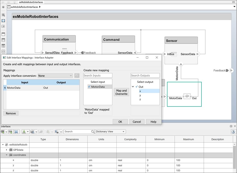
coordinates接口分配给 MotionData 端口。在 接口编辑器 中,选择coordinates接口。然后,右键点击 System Composer 画布上的端口,选择Apply selected interface coordinates。双击 Adapter 模块打开接口适配器。
在选择输入框中,选择
MotorData数据元素。在选择输出框中,选择x数据元素。点击映射和覆盖按钮。
您已通过映射 x 数据接口中的数据元素 coordinates,实现了从 MotorData 端口到 MotionData 端口的映射。
您可以使用 Adapter 模块对相似接口进行类似 N:1 连接的映射,此类适配器具有多个输入端口和一个输出端口。每个输入连接的数据元素都映射到输出连接的数据元素。
在
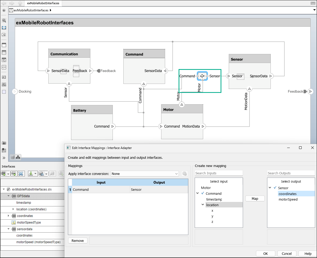
Motor组件的顶部创建一个电机输出端口。在Sensor、Motor和Command组件之间的连接上添加一个 Adapter 模块。以添加和删除组件端口相同的方式更改 Adapter 模块上的输入端口数量。有关详细信息,请参阅可视化构建架构。点击每个端口名称进行编辑和重命名。将
Sensor组件上的端口重命名为 Sensor,将Motor组件上的端口重命名为 Motor,将Command组件上的端口重命名为 Command。将
sensorData接口分配给 Sensor 端口。在 接口编辑器 中,选择sensorData接口。然后,右键点击 System Composer 画布上的端口,选择Apply selected interface sensorData。将
GPSData接口分配给命令端口。在接口编辑器中,选择GPSData接口。然后,右键点击 System Composer 画布上的端口,选择Apply selected interface GPSData。双击 Adapter 模块打开接口适配器。
在选择输入框中,选择
location数据元素。在选择输出框中,选择coordinates数据元素。点击映射按钮。
在 Adapter 模块上,与输入端口 Command 关联的数据元素 location 现在映射到与输出端口 Sensor 关联的数据元素 coordinates。现在,Sensor 组件上的 Sensor 端口可以与 Command 组件上的 Command 端口通信了。
使用单元延迟来打破代数循环
当连接两个在两个方向上都有端口连接的组件时,可能会发生代数环路。要打破代数循环,请使用 Adapter 模块在组件之间插入一个单位延迟。
在两个组件之间的连接上添加一个 Adapter 模块。
双击 Adapter 模块打开接口适配器。
从应用接口转换列表中选择
UnitDelay。
您可以通过点击 ![]() 图标来配置单位延迟。选项包括:
图标来配置单位延迟。选项包括:
初始条件 - 默认
0
有关详细信息,请参阅Remove Algebraic Loops。
Simulink 行为之间的速率转换
连接两个引用组件时,组件引用的 Simulink 模型可以具有不同的采样时间率。为了兼容性,请使用 Adapter 模块在组件之间插入一个速率转换。
在两个组件之间的连接上添加一个 Adapter 模块。
双击 Adapter 模块打开接口适配器。
从应用接口转换列表中选择
RateTransition。
您可以通过点击 ![]() 图标来配置速率转换。选项包括:
图标来配置速率转换。选项包括:
确保数据传输过程中的数据完整性 - 默认
true确保确定性数据传输(最大延迟)- 默认
true初始条件 - 默认
0
有关详细信息,请参阅数据传输表示和处理 (Simulink Coder)。
将 Adapter 模块用作 Merge 模块
使用 Adapter 模块作为 Merge 模块,以合并系统架构模型的多条消息线,或合并软件架构模型的多条消息线或多条信号和消息线。
在两个组件之间的连接上添加一个 Adapter 模块。
双击 Adapter 模块打开接口适配器。
从应用接口转换列表中选择
Merge。
有关详细信息,请参阅合并使用 Adapter 模块的架构的消息连接。
使用总线创建模式编写专属接口
当 Adapter 模块的输入端口由来自传入连接的接口类型化,且适配器的输出端口未定义任何接口时,您可以使用输入端口的接口元素为传出连接编写专属接口。专属接口是特定端口的专属接口,不在数据字典或模型字典中共享。无需预定义接口结构,您可以创建总线结构。
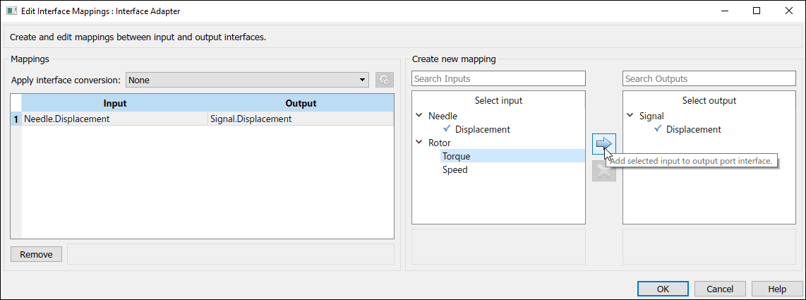
systemcomposer.openModel("SewingMachine");1.双击 Adapter 模块,以总线创建模式打开接口适配器。
2.点击 ![]() 按钮,将输入数据元素
按钮,将输入数据元素 Torque 添加到名为 Signal 的输出端口的接口。
3.从“选择输出”框中选择 Displacement 元素。点击 ![]() 按钮,从名为
按钮,从名为 Displacement 的输出端口的接口中删除输出数据元素 Signal。
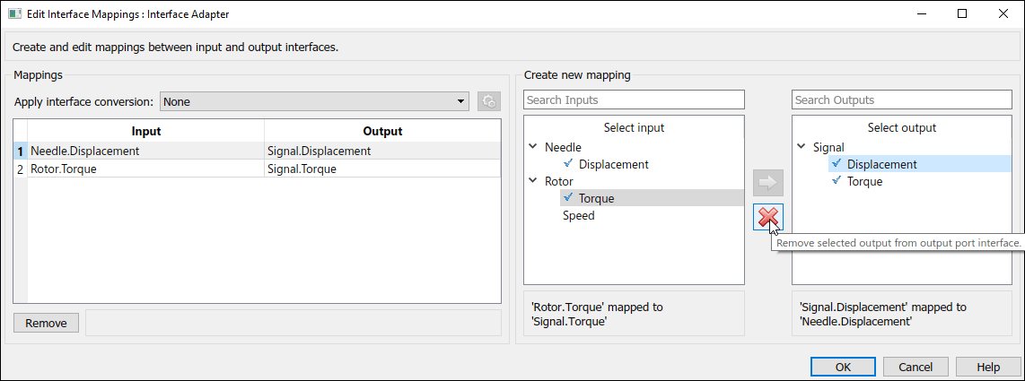
4.点击确定应用更改。
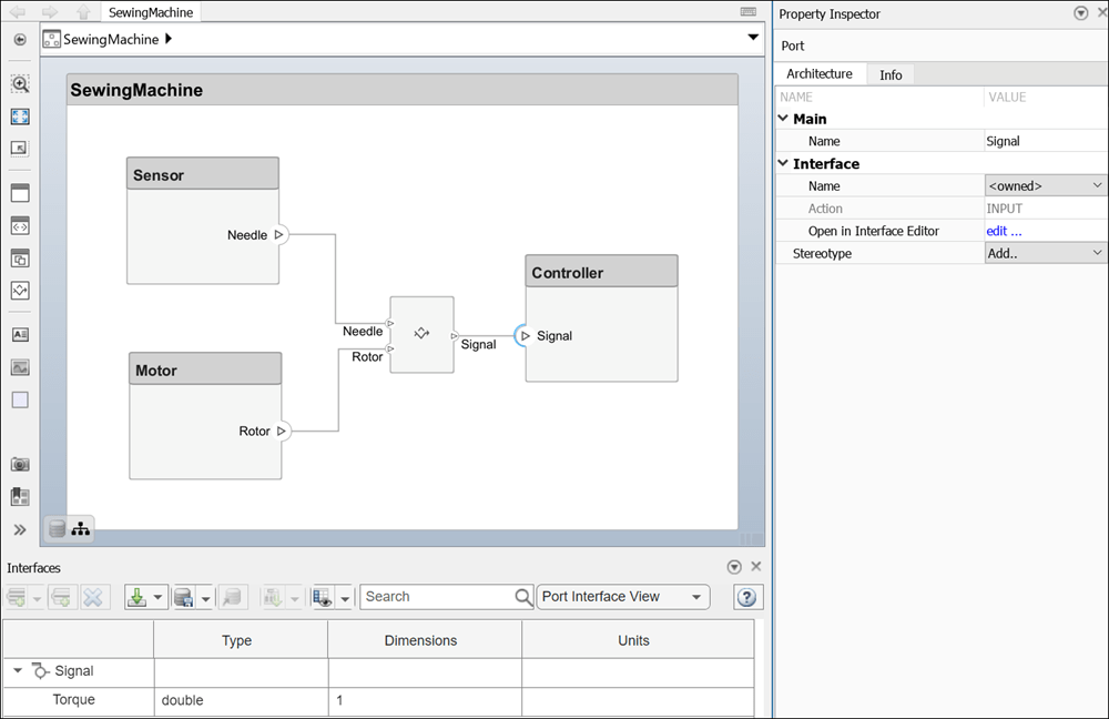
Adapter 模块输出端口上的专属接口传播到 Signal 组件上的连接输入端口 Controller。该专属接口包含一个元素:Torque。
要将一个专属接口转换为共享接口,请右键点击具有该专属接口的端口,然后选择 Convert to shared interface。