Model Reference Support for C2000 Processors
A model reference is a reference to another model using a Model block. These references create model hierarchy. Each referenced model has a defined interface that specifies the properties of its inputs and outputs. The defined interface makes the behavior of the referenced model independent of its context in the model hierarchy. For simulation and code generation, a referenced model executes like a single block, or atomic unit, when the parent model executes. Model references are ideal for code reuse, unit testing, parallel builds, and large components. They can also reduce file contention and merge issues. For more information, see Model References.
In C2000™ Microcontroller Blockset, you can now use all the driver blocks from C2000 library inside model reference expect for Software and Hardware interrupt, CLA task trigger, CLA subsystem, and Idle task.
Reference Existing Models
A model becomes a referenced model when a Model block in another model references it. Any model can function as a referenced model, and can continue to function as a separate model.
To reference an existing model in another model, follow these steps.
If the folder containing the model you want to reference is not on the MATLAB® path, add the folder to the MATLAB path.
In the referenced model, set Total number of instances allowed per top model to:
One- to use the model at most once in a model hierarchy.Multiple- to use the model more than once in a model hierarchy. To reduce overhead, specify Multiple only when necessary.Zero- to preclude referencing the model.
Create an instance of the Model block in the parent model. The new block is initially unresolved because it does not specify a referenced model.
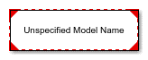
To open the Block Parameters dialog box, double-click the unresolved Model block.
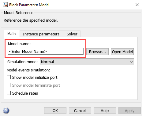
Enter the name of the referenced model in the Model name field.
Click OK. If the referenced model contains root-level inputs or outputs, the Model block displays corresponding input and output ports. For more, see Reference Existing Models
Things to Consider During Reference Modeling
Scheduling is considered only from the top model.
All the configuration parameters referred by driver blocks must be same across all the models. If they are not same, then behavior is undefined as we do not have control on which configuration will be picked by the block.
When using model reference and when function block is present in top level of child model, then you will not be able to generate the code for the child model directly.
Total number of instances allowed per top model is
One.For referenced models, go to Configuration Parameters > Diagnostics and set Insufficient maximum identifier length to
None, when maximum identifier length does not provide enough space to make global identifiers unique across models.When naming the top model and reference model, if the first 31 characters of the top and reference model name matches, you will encounter an compilation error. since all 31 characters are used to name the variables in the generated code.
So always try to have a unique names for top and reference model and try to keep the naming short.
Create Data Dictionary and Migrate the Model
This section describes how to create data dictionary to store model parameters and common configuration parameters references which can be used across parent and child models.
Configure your reference model with all the settings described in Reference Existing Models.
Open Model Properties. In the Model Properties dialog box, click New to create a data dictionary.
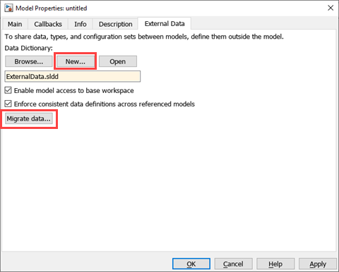
Name the data dictionary, save it, and click Apply.
Link model to data dictionary dialog appears. Select the appropriate option.

Click Migrate data.
Click Migrate in response to the message about copying referenced variables.
(Optional) Clear Enable model access to base workspace.
Click OK.
To open the dictionary, in the Simulink Editor, click the model data badge
 in the bottom left corner, then click the External Data link.
To inspect the contents of the dictionary, in the Model Explorer Model Hierarchy pane under the External Data node, expand the dictionary node.
Convert Configuration Set to Configuration Reference and Include in a New Model
As explained in the above section, all the configuration parameters referred by driver blocks must be same across all the models. If they are not same, then behavior is undefined as we do not have control on which configuration will be picked by the block. One way of doing this is to create configuration parameter references and refer the same across parent and child models. This ensures when ever there is change in the parameters, it is reflected across all the models.
In the top model, you must convert the active configuration set to a configuration reference:
Open the Model Explorer.
Go to Model Hierarchy > RefConfigModel > Configuration > Convert Active configuration to Reference.

To add it in the model, navigate to Model Hierarchy > RefConfigModel > Configuration > Add configuration Reference and click Activate.
Name the configuration reference. The associated sldd is selected to create a reference configuration set.
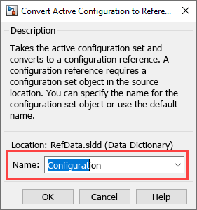
A configuration reference allows multiple models to use same externally stored configuration set.
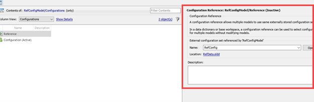
You can view the newly created reference configuration in Configuration Reference.
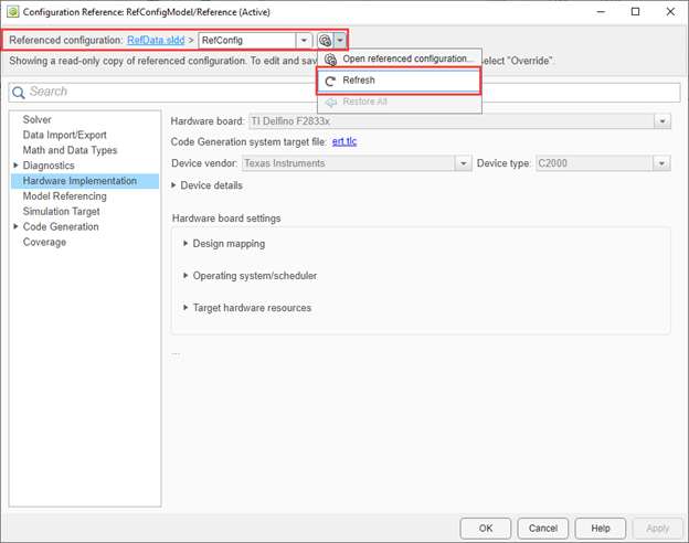
You can modify the reference configuration and share a Configuration with Multiple Models. For more information, see Share a Configuration with Multiple Models.
A predefined synchronous Referenced Model is available in Serial Communication Using SCI Blocks.
Configure Reference Model for Synchronous and Asynchronous Task
When you are working with reference models, the scheduling is considered only from the top model. When there is only synchronous task in the reference model, the sample time at which the reference model is called in the top model will determine the scheduling. However, if there are asynchronous task in the reference model, additional steps needs to be performed to trigger the same from the top model. This section explains how to configure a reference model when there is asynchronous task present in the reference model.
Open the top model. Enter the following command in MATLAB command prompt.
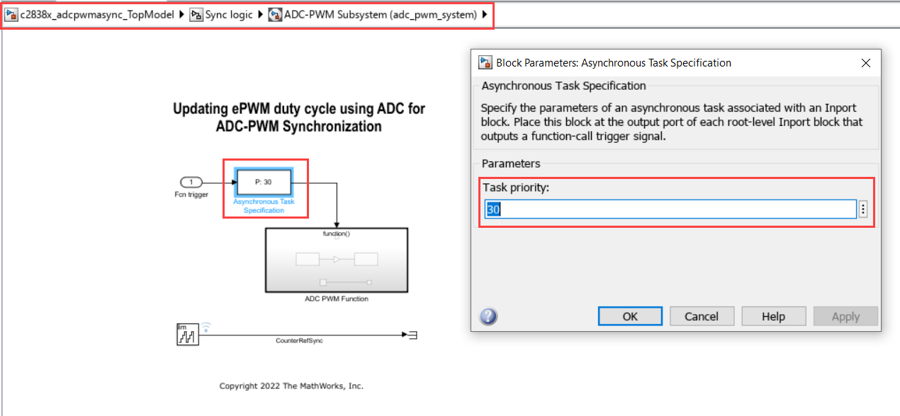
openExample('c2b/ADCPWMSynchronizationViaADCInterruptExample','supportingFile','c2838x_adcpwmasync_TopModel')Navigate to the path in the model where you are configuring the reference model (adc_pwm_system).
Verify that the asynchronous task specification block is added and it matches the task priority of the Hardware Interrupt triggering it in the top model.
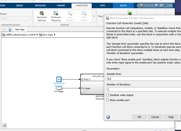
Verify that the inport triggering the asynchronous task has Output function call enabled.

Ensure the periodic rate in the reference model matches the top model.
Now this reference model contains both synchronous and asynchronous task.
Schedule the model through base rate for synchronous task (periodic) and interrupt for asynchronous task.
In the top model, right click on ADC-PWM Subsystem and select Block parameter (ModelReference). Verify Schedule rates parameter is enabled.
This options grows an inport with a scheduling icon and this can be configured to be triggered by a periodic task (in this example, function-call generator).

The output trigger from Hardware Interrupt block, is passed as an input to the previously configured asynchronous port in the reference model. With these configurations, the reference model with both synchronous and asynchronous task can be triggered from the top model.
Note
With the asynchronous task specification, you will not be able to generate code independently from the reference model.
See Also
Model References | Reference Existing Models | Share a Configuration with Multiple Models