Main Content

Using Sigma Delta Filter Module (SDFM) to Measure the Analog Input Signal

This example shows how to use the Sigma Delta Filter Module (SDFM) to measure the analog input signal for Texas Instruments™ C2000™ Microcontroller Blockset. Using this example, you can:

  • Configure the SDFM module to receive the digital bit stream from an external sigma delta modulator (SDM)

  • Display the filtered digital data

Introduction

This example uses ePWM and DAC blocks to generate clock and data signals which are provided as input to the external sigma delta modulator. The digital pulse stream from the sigma delta modulator is given as data input to the SDFM in the processor. The data filter output (DFLTx) is the digital 16-bit or 32-bit representation of the analog signal output from the DAC.

Required Hardware

  • F2807x or F2837x controlCARD/LaunchPad.

  • AMC1304EVM external Sigma Delta Modulator(SDM).

Hardware Connections

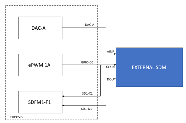
1. The output of the ePWM1A is provided as the clock input to the external SDM and the output of the DAC is provided as the analog data input to the external SDM.

2. The ePWM1A output is also provided as clock input to the SDFM module in the processor.

3. The digital data stream from the external sigma delta modulator is provided as the data input to the SDFM module.

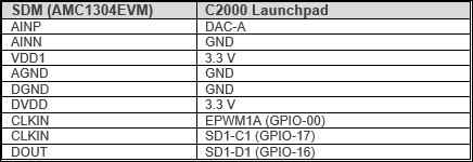
Connect the external SDM to the C2000 LaunchPad or ControlCARD as listed.

For the SDM AMC1304EVM, one must set jumper JP1 to the position labeled Ext.

Model

Open the model c28x7x_sdfm.slx.

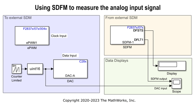
The ePWM1 is configured to give clock signal of 50% duty cycle and frequency in the range as required by external sigma delta modulator (SDM).

The input to DAC is varied from 1 to 300, and this will ensure that the analog output of DAC is varied in the input range as required by the SDM. The status of the data filter is viewed in the Display block. The varying input to the DAC and the digital data output from the SDFM can be viewed in the Scope block.

Configure and Run the Model

1. Open the SDFM example model. Go to the Modeling tab and press Ctrl+E to open the Configuration Parameters dialog box.

2. In the Configuration Parameters window, click Hardware Implementation > Hardware board and select the required hardware board.

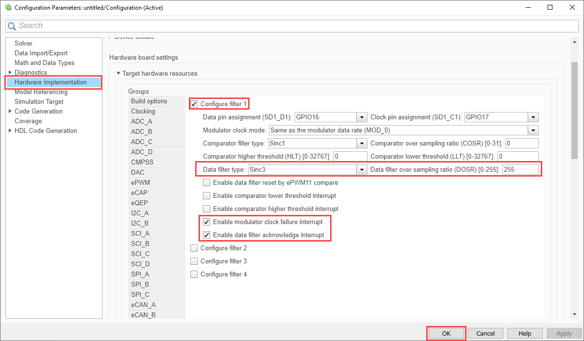
3. Browse to Target Hardware Resources > SDFM1 and select Configure filter 1. The digital filter settings for the filter channel 1 of SdfmReg1 is updated as shown below. Filter channel 1 of the SdfmReg1 with 16-bit data representation is configured for this example.

4. Ensure that Communication interface is set to Serial. The selection can be made at Configuration Parameters > Hardware Implementation > Target hardware resources > External Mode > Communication interface.

5. On the host computer, set the Serial port parameter to the COM port at Device Manager > Ports (COM & LTP) in Windows.

6. Click Apply and OK.

7. Open Hardware tab and click Monitor & Tune. Observe the input to DAC and the output of SDFM on the Scope block when the DFSTS output is 1.

Interpretation of DAC Analog Voltage Output and SDFM Digital Output

This section explains how to interpret the DAC output analog voltage and how to calculate the expected SDFM digital output. For example,

  • Analog output voltage of the DAC = 190mV

  • Input voltage range of the SDM = -250mV to 250mV

  • Ratio of input voltage to the max voltage range of SDM = (190-(-250))/500 = 440/500 = 0.88 or 88% The output pulse stream of 1s and 0s from SDM will contain 88% 1s.

For the below SDFM configuration, the output data range is (-32,768 to 32,767).

  • SDFM data filter type = Sinc3

  • Data filter Over Sampling Ratio = 256

  • Data representation = 16-bit

Since the input to SDFM contains a pulse stream with 88% 1s, the expected output (x) can be calculated as

(x-(-32768))/(32768*2) = 0.88

The expected SDFM output = 24,903 The actual SDFM output = 2.52 * 10^04 One can expect an error of around 1% or less in the digital output due to variations at the DAC output due to operations at such low voltages and due to the connections used.

Other things to try

You can configure the SDFM comparator filter in the configuration parameters, Target Hardware Resources > SDFM1 and check the status of the comparator filter flags by enabling the Enable comparator output in the block parameter.

More About

F2807x/F2837xD/F2837xS/F28004x/F28003x/F2838x/F28p65x SDFM