Set Up CAN Communication with Target Hardware
This topic explains how to set up Controller Area Network (CAN) communication between C2000™ target hardware and your host computer using Vector hardware. CAN communication allows for efficient data transfer, which is especially useful in embedded control applications. Follow these steps to prepare your system
Prerequisites
Ensure that the Vector Hardware is correctly installed and recognized in the Windows® Device Manager.

Steps to Configure CAN Communication
Install Vector XL Library.
Download and install the latest Vector XL Library from the Vector website.
Copy
vxlapi64.dllfrom the installation folder (e.g.,C:\Softwares\Vector_Driver_Setup_9_3_0\Common) toC:\Windows\System32.
Resolve Driver Issues (if applicable):
Download and install XL Driver Library Setup version 20.30.14.
Download and install the Vector driver setup for Windows 10 and 11.
Copy
vxlapi64.dlltoC:\Windows\System32andvxlapi.dlltoC:\Windows\SysWOW64.Restart your computer.
Verify CAN device in MATLAB®. Open MATLAB and execute
canChannelListin the command window to verify device detection.For more information on how to connect the hardware device with MATLAB, see How to Connect my hardware device from MATLAB
Configure the CAN device in Vector software.
Run
vcanconf.exefrom the Vector driver installation.Right-click on the application, select Add application, and name it MATLAB.
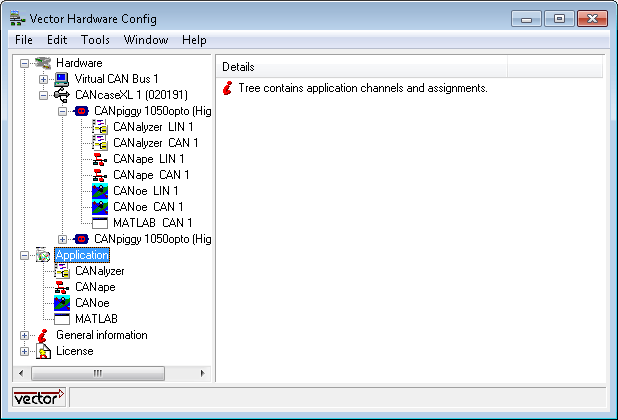
Assign CAN 1 to the first CAN piggy hardware device.
Adjust the baud rate to match the CAN baud rate in your Simulink® model using Target Preferences settings.
Verify the baud rate in Simulink.
Open the model. Go to Configuration Parameters dialog box, select the desired Hardware board and verify the CAN baud rate. The default baud is
1 Mbits/sec.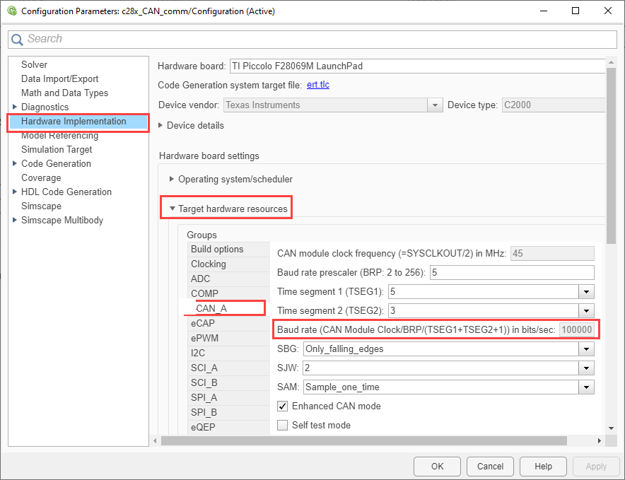
Following these steps ensures that CAN communication is established between your host computer and the C2000 target hardware. For more details on CAN communication using Simulink, see Communication Using CAN Blocks.