Getting Started with ArduPilot Serial Receive and Transmit Blocks
R2026bThis example shows how to configure two ArduPilot® telemetry ports for bidirectional loopback communication using Serial Transmit and Serial Receive blocks in Simulink®.
In the example, you configure matching serial settings and align the Serial Receive block parameters with the transmitted data. Then, you verify the exchanged values by simulating in Monitor & Tune or Connected IO mode.
Required Hardware
This example requires the following hardware:
ArduPilot Series flight controller
Micro USB Type-B cable
JST-GH 6-pin connector
Configure Software and Hardware for ArduPilot
Install the UAV Toolbox Support Package for ArduPilot Autopilots. For more information, see Get Started with UAV Toolbox Support Package for ArduPilot Autopilots.
Set up and configure your ArduPilot hardware. For details, see setup and configuration.
Load Project
Open the example project.
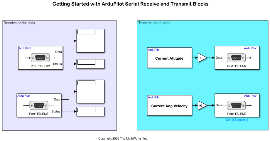
openExample("ardupilot/SerialDataReceiveTransmitExample") The project contains the Simulink model ReceiveTransmitSerialData.The model connects Serial Transmit blocks on TELEM2 and TELEM3 to send attitude and angular velocity data, with corresponding Serial Receive blocks on the opposite ports.
Set Up Loopback Wiring
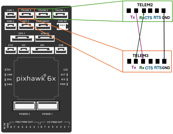
Create a loopback communication path between TELEM2 and TELEM3 ports so that each port receives the data that the other port transmits. On the ArduPilot hardware:
Connect the
Txpin onTELEM2to theRxpin onTELEM3.Connect the
Txpin onTELEM3to theRxpin onTELEM2.Connect the ground (
GND) pins ofTELEM2andTELEM3to establish a common signal reference.If you use hardware flow control, connect the request-to-send (
RTS) pin onTELEM2to the clear-to-send (CTS) pin onTELEM3.Connect theRTSpin onTELEM3to theCTSpin onTELEM2.
In the Simulink model, the Serial Receive block on TELEM3 receives attitude data from TELEM2, and the Serial Receive block on TELEM2 receives angular velocity data from TELEM3.
Configure Serial Ports Settings
Configure the serial port settings in the model for TELEM2 and TELEM3 to match the hardware and model configurations
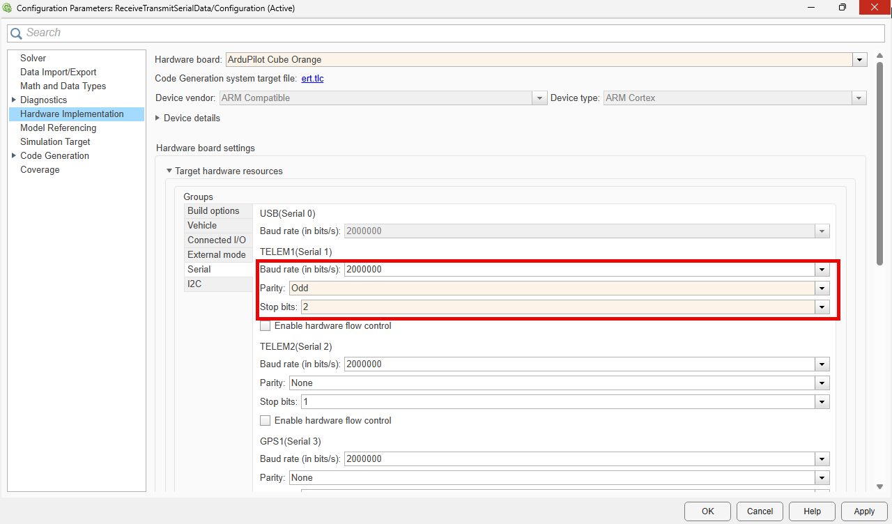
To review the serial port mapping for the selected ArduPilot hardware board, on the Modeling tab, click Model Settings. The hardware settings map logical serial ports to physical connectors, such as
TELEM1,TELEM2, andTELEM3.In the Configuration Parameter dialog box, in the Hardware Implementation pane, set Hardware board to the ArduPilot controller you are using.
In Hardware board settings, in Target hardware resources, in the Serial tab, set Baud rate to
2000000, Parity toOdd, Stop bits to2.Save these parameter values for
TELEM2andTELEM3.
These settings align the serial communication parameters on both telemetry ports consistent with the model configuration.
If the model uses hardware flow control, select Enable hardware flow control for both ports. Then connect the RTS and CTS pins as described in the loopback wiring section, because the ports use those signals to control data transfer.
Configure Sending and Receiving Angular Velocity and Attitude
Configure the Serial Transmit and Serial Receive blocks so that each telemetry port sends one signal and receives the signal from the opposite port.
Set the Serial Transmit block that transmits attitude data to use
TELEM2.Set the Serial Receive block that receives attitude data to use
TELEM3.Set the Serial Transmit block that transmits angular velocity data to use
TELEM3.Set the Serial Receive block that receives angular velocity data to use
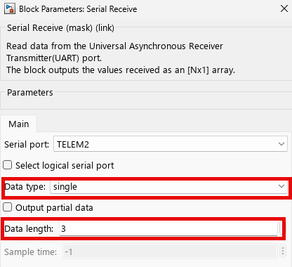
TELEM2.In each Serial Receive block, set Data type and Data length to match the signal from the corresponding Serial Transmit block. For example, if the transmit path sends a 1-by-3 vector of single-precision values, set Data type to
singleand Data length to3.
6. If the Serial Receive and Serial Transmit block requires a logical serial port, select Select logical serial port check box. Then from the Serial logical port list, select the port.
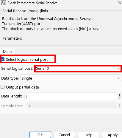
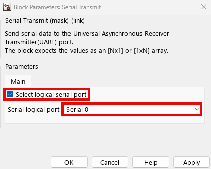
Matching Data type and Data length enables the Serial Receive block to convert the incoming bytes into the expected signal. If Data type or Data length do not match, the Serial Receive block misinterprets the byte stream and produces incorrect values.
Run and Verify Loopback Communication
Verify that the serial communication path transfers data between the TELEM2 and TELEM3 ports.
Run the model in Monitor & Tune or Connected IO mode on the target hardware. The model transmits attitude data from TELEM2 to the Rx pin on TELEM3 and transmits angular velocity data from TELEM3 to the Rx pin on TELEM2.
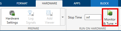

To compare the transmitted and received values, use the Display blocks in the model. Matching values confirm that the wiring, serial port configuration, and block parameters are consistent across both communication paths.
If the displayed values do not match, verify the Tx and Rx connections. Then verify that both telemetry ports use the same Baud rate, Parity, Stop-bits, and flow-control settings. Also verify that each Serial Receive block uses the same Data type and Data length settings as the signal from the corresponding Serial Transmit block.
After you confirm that the serial blocks exchange matching data, you can reuse the same wiring and port configuration to exchange sensor, telemetry, or command data in your own applications. To extend this workflow to custom frame-based serial communication, see Send and Receive Custom Frame-Based Serial Data with ArduPilot.
See Also
Send and Receive Custom Frame-Based Serial Data with ArduPilot

