Send and Receive Custom Frame-Based Serial Data with ArduPilot
R2026bThis example shows how to send and receive custom frame-based serial data between a host computer and an ArduPilot® flight controller using the UAV Toolbox Support Package for ArduPilot Autopilots®. The example uses a request-response protocol in which a MATLAB® script on the host computer sends a data request, and the flight controller responds with the requested attitude or angular velocity data.
The Simulink® model of this example implements the communication by using Serial Receive and Serial Transmit blocks from UAV Toolbox Support Package for ArduPilot Autopilots. The host sends a command frame that contains a header and a payload. The flight controller decodes the frame, processes the request, and returns the corresponding sensor data with an output header.
Required Hardware
This example requires the following hardware:
ArduPilot Series flight controller
Micro USB type-B cable
Configure Software and Hardware for ArduPilot
Install the UAV Toolbox Support Package for ArduPilot Autopilots. For more information, see Get Started with UAV Toolbox Support Package for ArduPilot Autopilots.
Set up and configure your ArduPilot hardware. For details, see setup and configuration.
Verify that the flight controller has ArduPilot firmware version 4.6.2 installed.
Load Project
Open the example project:
openExample("ardupilot/SendReceiveCustomFrameBasedSerialDataExample")The project contains a Simulink model apSerialRxTx_Demo model and MATLAB scripts that define message headers, request command data, and apply script-defined parameters to the model.
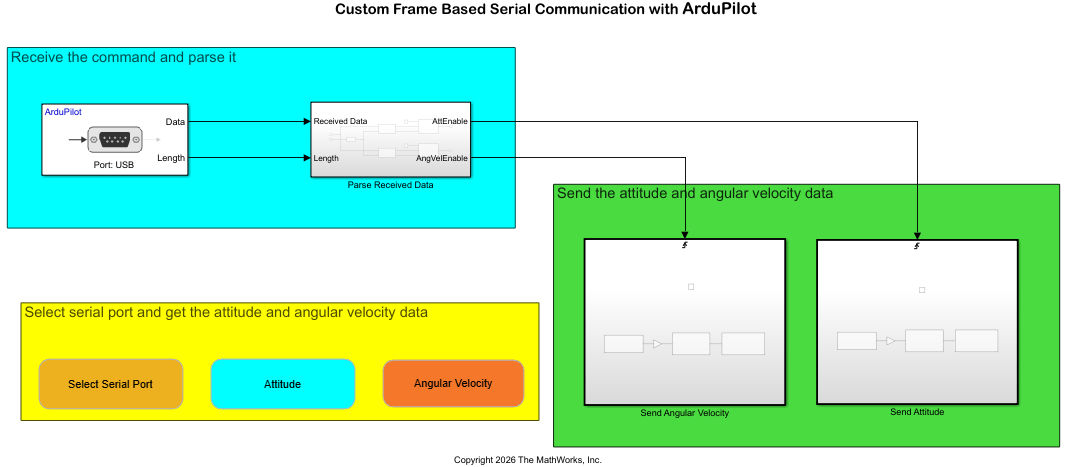
apSerialRxTx_Demo— Simulink model deployed to the flight controller. The model sends attitude and angular velocity data over USB after the host computer sends a request. In the area marked "Receive the command and parse it", the Serial Receive block gets the raw data and passes it to the Parse Received Data subsystem. The Protocol Decoder block identifies the data type by matching predefined headers and extracts the corresponding attitude or angular velocity data. The Protocol Encoder block formats the outgoing data by adding output headers before transmission. MATLAB displays the received data in the Command Window.
getAttitudeData.m— MATLAB script that requests and displays attitude data (yaw, pitch, roll angles).getAngularVelocity.m— MATLAB script that requests and displays angular velocity data (x, y, and z axes).initializeModel.m— MATLAB script that defines the headers for inputs, outputs, encoder, and decoder. ThesetBlockParametersfunction applies these settings to the model. You can use the file as provided or modify the headers, which update automatically in the model.setBlockParameters.m— MATLAB function that applies parameter values to the model based on the initialization script.
You can run the example without modifying any scripts. To customize the communication protocol (for example, changing headers or command values), update the initialization script and rerun it. The parameter-setting function applies these changes to the model automatically.
Configure the Model for ArduPilot Hardware
Before deploying the model, verify the hardware and model configuration settings for the target ArduPilot flight controller. This setup connects the host computer to the flight controller and keeps the serial communication parameters consistent across the model and scripts.
1. Connect your ArduPilot board to the host computer using the USB cable.
2. Open the apSerialRxTx_Demo model. Use this pre-configured model with ArduPilot Series boards.
3. To open the configuration parameters, on the Modeling tab, click Model Settings.
4. In the Configuration Parameters dialog box, select the Hardware Implementation pane and set Hardware board to the ArduPilot controller you selected during the hardware setup.
5. To save your changes and close the dialog box, click Apply, then click OK.
Configure Serial Port
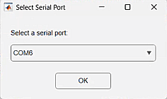
To select the COM port used by the flight controller, in the apSerialRxTx_Demo model, click Select Serial Port and select the COM port from the list.
Deploy Model to ArduPilot Hardware
After you deploy the model, it runs directly on the ArduPilot flight controller and communicates with the host computer through a USB serial connection. The flight controller responds to host requests by using a custom frame-based serial protocol and returns the requested data.
Open the
Custom Frame Based Serial Communication with ArduPilotmodel.To deploy the model to the flight controller, on the Hardware tab, in the Mode section, select Run on board. In the Deploy section, click Build, Deploy & Start.

The Simulink Editor displays deployment status in the lower-left corner while the model builds and deploys to the hardware.
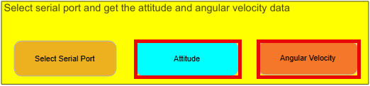
3. To receive attitude and angular velocity data from the flight controller, in the area marked "Select serial port and get the attitude and angular velocity data," click Attitude and Angular Velocity.
MATLAB displays the received values in the Command Window.
Header for angular velocity data: ANG_VEL_DATA
Angular velocity data(x | y | z) in degree/s: -7.7929 | -0.8567 | -15.1254
Header for attitude data: ATT_DATA
Attitude data(x | y | z) in degree/s: 75.4789 | -26.8449 | -1.9855
After you verify serial communication with the flight controller, you can modify the model to send and receive different data types or integrate serial communication into a larger flight control workflow. To adapt this example for different data, modify the headers and command data in the initialization script (initializeModel.m) and rerun the script to apply the changes to the model.
See Also
Getting Started with ArduPilot Serial Receive and Transmit Blocks

