Tune Position and Yaw Setpoints in External Mode and Log Flight Data Using PX4 SIH
R2026bThis example shows how to deploy a custom position and attitude controller on PX4 hardware using the UAV Toolbox Support Package for PX4 Autopilots with Simulation-in-Hardware (SIH). Tune position and yaw setpoints wirelessly in External Mode and log flight data using PX4 uLOG. You learn how to tune multicopter setpoints in real time, establish wireless communication using telemetry modules, and analyze logged flight data to evaluate controller performance.
This example combines the following capabilities to create a controller tuning workflow on PX4 hardware:
SIH on hardware – The PX4 firmware runs a built-in quadrotor dynamics model on the target hardware, enabling controller testing without flying the vehicle.
Wireless External Mode (tuning only) – A telemetry radio link between the development computer and the PX4 board enables real-time parameter tuning without a physical connection. In this workflow, External Mode is used only to tune setpoints. Signal logging is handled separately using PX4 uLOG.
uLOG flight data logging – Records controller and vehicle state data on the PX4 SD card for post-run analysis.
During External Mode operation, slider blocks in the Simulink model command the desired XY position, altitude, and yaw setpoints. The deployed controller tracks these commands using cascaded PID control loops. After the session, analyze the logged data to evaluate tracking performance and tune the PID gains.
In this example, wireless External Mode is used only for tuning (adjusting parameters such as position and yaw setpoints). For signal logging, the example uses PX4 uLOG with the simulink_custom_message topic. Do not use External Mode for signal logging over the wireless telemetry link, as this can cause communication failures due to bandwidth limitations of the telemetry radio channel.
Note: The TELEM modules used in this example do not support AES encryption. If multiple telemetry modules within range use the same communication parameters, other modules might receive transmitted data. Configure unique communication parameters and consider using telemetry modules that support AES encryption.
Prerequisites
1. If you are new to Simulink, watch the Simulink Quick Start video.
2. If you have not done so already, install the UAV Toolbox Support Package for PX4 Autopilots. Select the installation topic appropriate for your operating system.
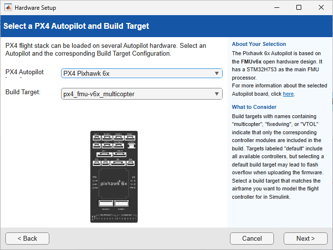
At the Select a PX4 Autopilot and Build Target step of installation, specify these options::
PX4 Autopilot board —
PX4 Pixhawk 6xBuild Target —
px4_fmu-v6x_multicopter
For more information on board and the build targets, see SIH on Flight Controller Hardware.
3. Before running Software-In-The-Hardware (SIH), add the following line to the default PX4 board configuration file for the target hardware:
CONFIG_MODULES_SIMULATION_SIMULATOR_SIH=y
Save the updated .px4board file. Then in the Hardware Setup screen select the file using the Custom PX4Board File option, and use the multicopter CMake variant. For more information about modifying PX4 build target files and enabling or disabling PX4 modules see Disabling Modules in PX4board Build Target File. Then run the hardware setup screen with the multicopter variant of cmake.
4. In QGroundControl (QGC), configure the following for SIH operation:
Set airframe to SIH Quadcopter X.
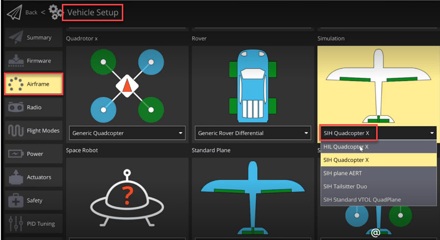
Navigate to Vehicle Setup > Parameters and set the following parameters.

Set
COM_RAM_MAXto-1.Set
COM_CPU_MAXto-1.Check the
MAV_X_CONFIGparameters and ensure the TELEM port where the air module is connected in Hardware is not used in any of those parameters. If set disable it.
5. Install Mission Planner. This example uses Mission Planner to configure the telemetry radio modules required for wireless External Mode communication.
Required Hardware
Telemetry radio pair (air module and ground module) for wireless external mode communication
USB cable
PX4 Simulation-In-Hardware (SIH)
PX4 Simulation-In-Hardware (SIH) is a simulation mode in which the PX4 firmware runs a built-in vehicle dynamics model directly on the autopilot hardware. Unlike Software-in-the-Loop (SITL), which runs the PX4 firmware and a dynamics model on a development computer, SIH executes entirely on real autopilot hardware and uses the internally simulated vehicle state instead of physical sensor data.
SIH enables you to verify flight controller algorithms on the actual target hardware without requiring:
An external simulator (such as jMAVSim)
A physical vehicle or propellers
Actual flight
SIH is useful for iterating on controller designs because you work directly with the hardware that runs your deployed code, while the firmware's internal dynamics model provides realistic vehicle dynamics feedback.
Note: The built-in SIH dynamics model is not available on all PX4 hardware targets due to memory constraints on some boards. Verify that your PX4 hardware supports SIH before using this example. PX4 Pixhawk 6c and similar boards with sufficient flash memory support SIH by default.
Model Overview
Open the WirelessExtModeSIH.slx model.
modelName = "WirelessExtModeSIH";
open_system(modelName)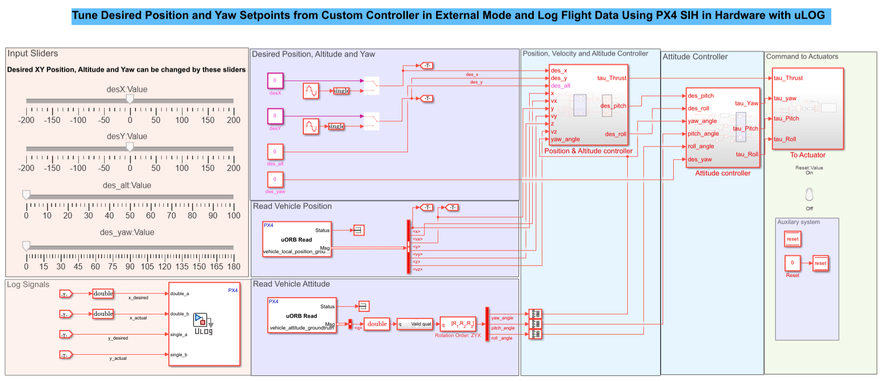
The model consists of these components:
Input Sliders — Dashboard slider blocks that set desired XY position, altitude, and yaw setpoints. You adjust these in real time during external mode operation.
Desired Position, Altitude, and Yaw — Formats the slider outputs into setpoint commands for the controller.
Read Vehicle Position — Reads the estimated vehicle state (position, velocity, and attitude) from the SIH-simulated sensor data on the PX4 board.
Position, Vehicle and Attitude Controller — Cascaded PID controller that computes thrust and torque commands from position and attitude errors.
Command to Actuators — Mixer that maps thrust and torque commands to individual motor outputs.
Log Signals — Displays vehicle position and attitude data in real time and logs data using uLOG.
Model Initialization Script
The model uses an initialization script, initializeModel.m, to define the sample time and PID controller gains for the position, velocity, altitude, and yaw controllers. Run this script before deploying the model to load the required parameters into the MATLAB workspace.
initializeModel
The script sets platform-specific PID gains to account for timing differences between Windows and Linux development environments.
Position and Altitude Controller
The Position & Altitude Controller subsystem implements a cascaded control structure with an outer position loop and an inner velocity loop.
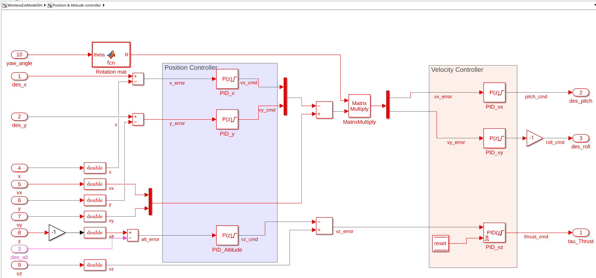
Outer position loop:
PID_x and PID_y — Compute velocity commands in the X and Y directions from position errors.
PID_Altitude — Computes a vertical velocity command from altitude error.
Inner velocity loop:
PID_vx and PID_vy — Convert horizontal velocity commands to desired pitch and roll angles. A rotation matrix based on the current yaw angle transforms body-frame velocity errors to the correct attitude references.
PID_vz — Computes the thrust command from vertical velocity error.
Attitude Controller
The Attitude Controller subsystem computes torque commands to track the desired roll, pitch, and yaw angles.
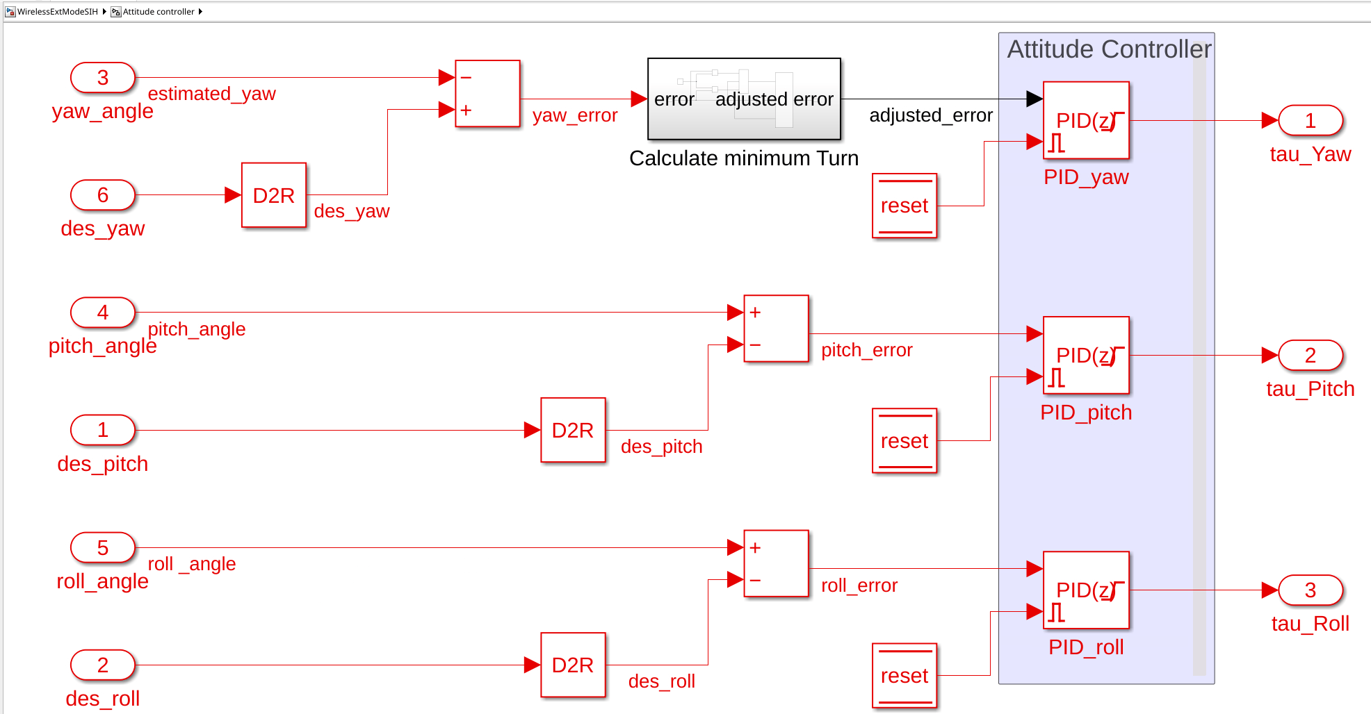
PID_yaw — Computes the yaw torque from yaw error. The Calculate minimum Turn block wraps the yaw error to ensure that the controller takes the shortest rotation path to the desired heading.
PID_pitch — Computes the pitch torque from pitch angle error.
PID_Roll — Computes the roll torque from roll angle error.
The desired roll and pitch angles come from the position controller output. The desired yaw angle comes from the input slider.
Command to Actuators
The To Actuator subsystem maps the thrust and torque commands to individual motor speeds using a mixer matrix for an X-configuration quadcopter.
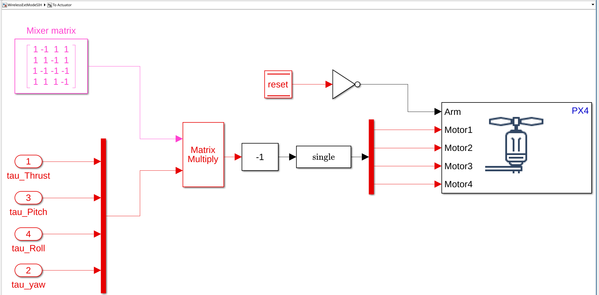
The mixer matrix distributes the collective thrust and the roll, pitch, and yaw torques to the four motors. The motor commands are converted to single precision before being sent to the PX4 actuator output block. The Arm signal controls whether the motors are active.
Configure Telemetry Radio Modules
Wireless External Mode requires a pair of telemetry radio modules (air and ground). Configure both modules to use the same baud rate as the External Mode communication channel.
To configure the telemetry modules:
Connect the ground module to the development computer using a micro USB cable.
Connect the air module to the hardware board serial port (TELEM1 or TELEM2) and power the hardware board.
Open Mission Planner and navigate to Setup > Optional Hardware > SiK Radio.
Select the COM port connected to the ground module and set the baud rate to
57600(default) or115200. Verify that Connect is not active.Click Load Settings. The Local and Remote sections populate with the current radio settings, including the firmware version.
Set the radio baud rate to match the baud rate that you plan to use for External Mode communication (for example,
115200). If other telemetry radios are operating nearby, change the Net ID to a unique value. The default Net ID is25.Click Copy Required Items to Remote, and then click Save Settings.
Close Mission Planner.
Note: Both telemetry modules must use the same baud rate. The baud rate must also match the value configured for External Mode communication in the Simulink model. Common baud rate values are 57600 and 115200.
Configure External Mode Communication in Simulink
After the telemetry modules are configured, set up the Simulink model to communicate over the serial link. These settings are pre-configured in the model. Update the serial port and baud rate to match your telemetry hardware.
Open the Simulink model. On the Simulink Toolstrip, click Modeling > Model Settings.
In the Configuration Parameters dialog box, navigate to Hardware Implementation > Target hardware resources > External mode.
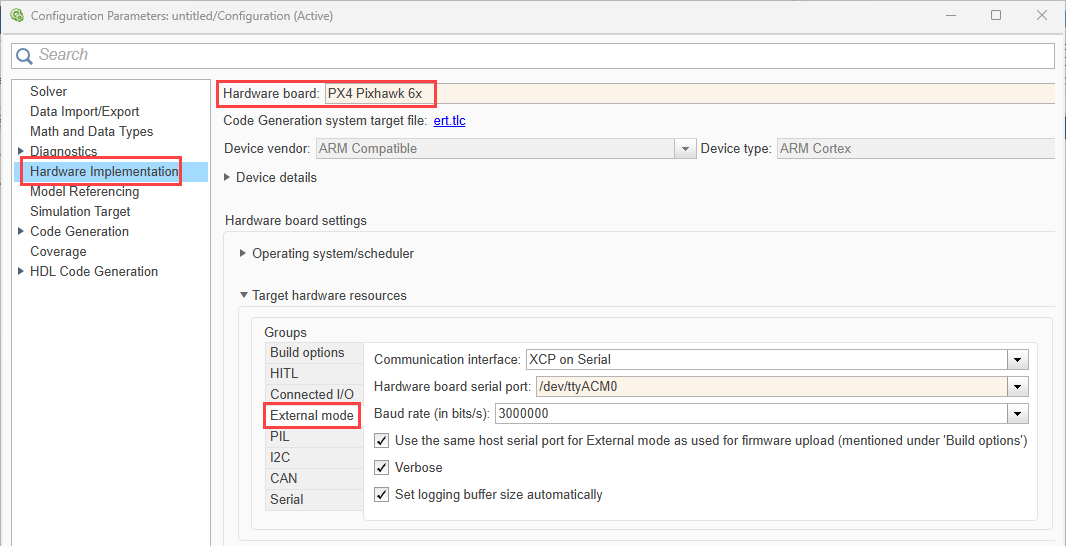
3.Select the Hardware board serial port to the serial port where the air module is connected (for example, /dev/ttyS4). For the correct serial port name, see Serial Port Names and Corresponding Labels on PX4 Flight Controller Boards.
4. Set Baud rate (in bits/s) to the same value configured on the telemetry modules (for example, 57600).
5. If listed, clear the Use the same host serial port for External mode as used for firmware upload option.
6. Set Host Serial port to the COM port on the development computer where the ground telemetry module is connected (for example, COM9).
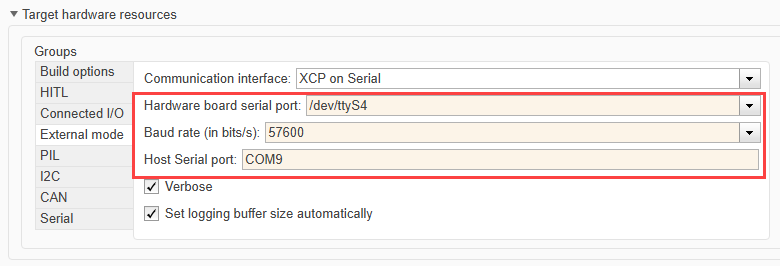
7. Click Apply and Ok.
Deploy and Run the Controller in External Mode
To deploy the model and run it in external mode with SIH:
To run the quadcopterPositionController.slx model in Monitor & Tune mode:
From the Simulink Toolstrip, select the Hardware tab.
Verify that the Mode section contains a Run on board button. If it instead contains a Connected IO button, click Connected IO, then Run on board (External mode).
In the Run on Hardware section, click Monitor & Tune
 .
.
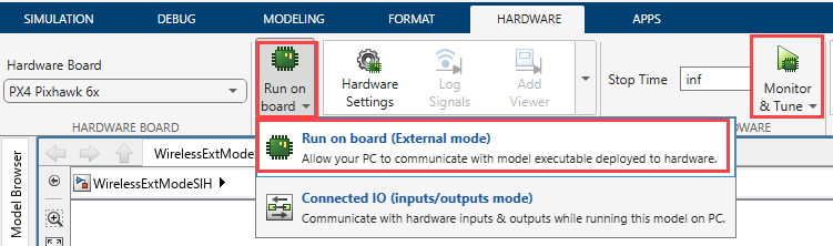
Simulink builds the model, deploys the generated code to the PX4 hardware, and establishes the wireless external mode connection.
After the connection is established, the PX4 firmware uses its built-in SIH dynamics model to simulate vehicle behavior. The simulated vehicle responds to your controller commands.
Tune Position and Yaw Setpoints
During external mode operation, use the dashboard slider blocks to command the vehicle to different positions and yaw angles:
Slider | Parameter | Range |
| Desired X position (m) | –200 to 200 |
| Desired Y position (m) | –200 to 200 |
| Desired altitude (m) | 0 to 200 |
| Desired yaw angle (deg) | 0 to 180 |
Adjust the sliders and observe the real-time vehicle response in the Display and Scope blocks within the model. The controller tracks the commanded setpoints using the cascaded PID architecture.
Configure uLOG Logger for Simulink Custom Message
Before you can log controller signals to the PX4 SD card, register the custom uLOG message topic in the PX4 logger configuration. The PX4 logger reads a file named logger.txt on the SD card to determine which additional topics to record.
To configure the logger:
Remove the SD card from the PX4 autopilot and mount it on your development computer.
Navigate to the root directory of the SD card and open or create the file
etc/logging/logger.txt.Add the following line to register the Simulink custom message topic:
simulink_custom_message
Save the file and reinsert the SD card into the PX4 autopilot.
Power cycle the PX4 board so that the logger reads the updated configuration.
After this configuration, the PX4 logger records the simulink_custom_message topic alongside standard flight data whenever logging is active. You only need to perform this step once; the configuration persists on the SD card across power cycles.
For more information on uLOG logging, see Log Simulink Signals Using PX4 ULog.
Log Flight Data Using uLOG
Logging enables you to evaluate how well the multicopter follows commanded setpoints and identify areas for controller tuning. The model logs flight data to the PX4 SD card using the uLOG logging mechanism with the simulink_custom_message topic.
The logged fields in the simulink_custom_message topic include:
Field | Description |
| Commanded X position setpoint (m) |
| Estimated X position (m) |
| Commanded Y position setpoint (m) |
| Estimated Y position (m) |
Note: Ensure that you have configured the simulink_custom_message topic in the logger.txt file on the SD card before the flight session, as described in the previous section. \
To retrieve and analyze the flight log:
Stop the External Mode session in Simulink.
Remove the SD card from the PX4 hardware, or use QGroundControl to download the log file.
Locate the
.ulglog file in thelogdirectory on the SD card.Use the
ulogreaderfunction to import the uLOG data into MATLAB. For more information, seeulogreader.
Analyze Tracking Performance and Tune PID Gains
After you retrieve the logged data, read the simulink_custom_message topic from the uLOG file and compare the desired and actual position values to evaluate controller performance.
Plot the desired and actual position for each axis:
% Read the uLOG file
logData = ulogreader("log_file.ulg");

% Extract Simulink custom message data
sihData = readTopicMsgs(logData,"simulink_custom_message");

% Convert timestamps to seconds (start from t = 0)
t = (sihData.timestamp - sihData.timestamp(1)) * 1e-6;

% Plot X position: desired vs actual
figure
subplot(2,1,1)
plot(t, sihData.x_actual, 'b', 'DisplayName', 'Actual X')
hold on
plot(t, sihData.x_desired, 'r--', 'DisplayName', 'Desired X')
xlabel('Time (s)')
ylabel('X Position (m)')
legend
title('X Position Tracking')
grid on

% Plot Y position: desired vs actual
subplot(2,1,2)
plot(t, sihData.y_actual, 'b', 'DisplayName', 'Actual Y')
hold on
plot(t, sihData.y_desired, 'r--', 'DisplayName', 'Desired Y')
xlabel('Time (s)')
ylabel('Y Position (m)')
legend
title('Y Position Tracking')
grid on
From the plots, you can analyze
Tracking accuracy — How closely the actual position follows the commanded setpoints.
Rise time — How quickly the vehicle reaches the new setpoint after a command change.
Overshoot — Whether the vehicle overshoots the target position before settling.
Steady-state error — Any persistent offset between the desired and actual position.
Other Things to Try
Increase the position setpoint step size and observe how the controller responds to larger position changes. Compare the rise time and overshoot with smaller setpoint changes.
Modify the yaw setpoint while commanding position changes and observe how the controller maintains position tracking during heading changes.
Configure different telemetry radio baud rates (for example, 57600 and 115200) and compare the responsiveness of External Mode communication.

