Simulation 3D UAV Vehicle
R2026bSimulate UAV in 3D environment using Unreal Engine
Simulation 3D UAV Vehicle block
To add a block to a model, double-click the canvas and start typing the block name. Then, select the block from the list.
Libraries:
UAV Toolbox /
Simulation 3D
Description
Note
Simulating models with the Simulation 3D UAV Vehicle block requires Simulink® 3D Animation™.
The Simulation 3D UAV Vehicle block simulates an unmanned aerial vehicle (UAV) in a 3D environment rendered using the Unreal Engine® from Epic Games®. The block supports quadcopter, fixed-wing, and custom UAV types. The block uses the input (X, Y, Z) position and input (yaw, pitch, roll) attitude of the UAV in the simulation.
To use this block:
Add a Simulation 3D Scene Configuration block to your model.
Connect the
TranslationandRotationinput ports.Set the block priority to
-1(right-click the block, select Properties, then on the General tab set Priority) so that it executes before the Simulation 3D Scene Configuration block (priority0).Set Sample time to
-1to inherit the sample time from the Simulation 3D Scene Configuration block.
For more information about execution order, see Block Execution Order.
Examples
Open the tiltRotorUAVModel.slx Simulink® model.
open_system("tiltRotorUAVModel")
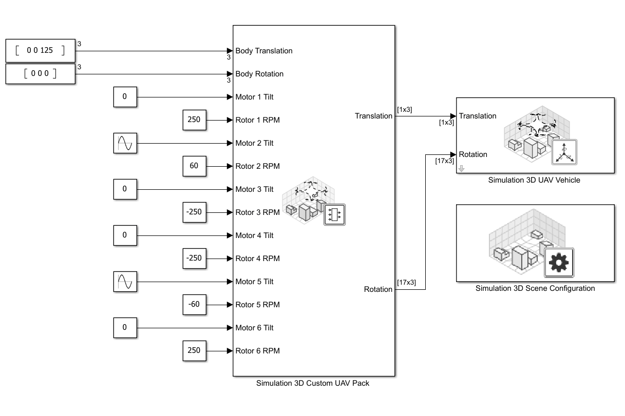
This model uses the Simulation 3D UAV Vehicle block to simulate a custom Hexarotor UAV in 3D environment. The Type parameter is specified to Custom, and the Path to custom mesh is specified to /MathWorksUAVContent/UAVs/HexaRotorUAV/HexaRotor.HexaRotor.
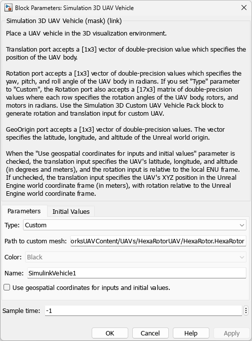
This model uses the Simulation 3D Custom UAV Pack block to generate the translation and rotation inputs. The block is configured to accept the body translation, body rotation, tilt angles for motors 1 to 6, and angular velocities of rotors 1 to 6.
The Hexarotor custom mesh is configured with the bone hierarchy that is shown in the following image. For more details on how to configure custom UAV mesh for simulation in Unreal Engine, visit Prepare Custom UAV Vehicle Mesh for Unreal Engine Scenario Simulation.
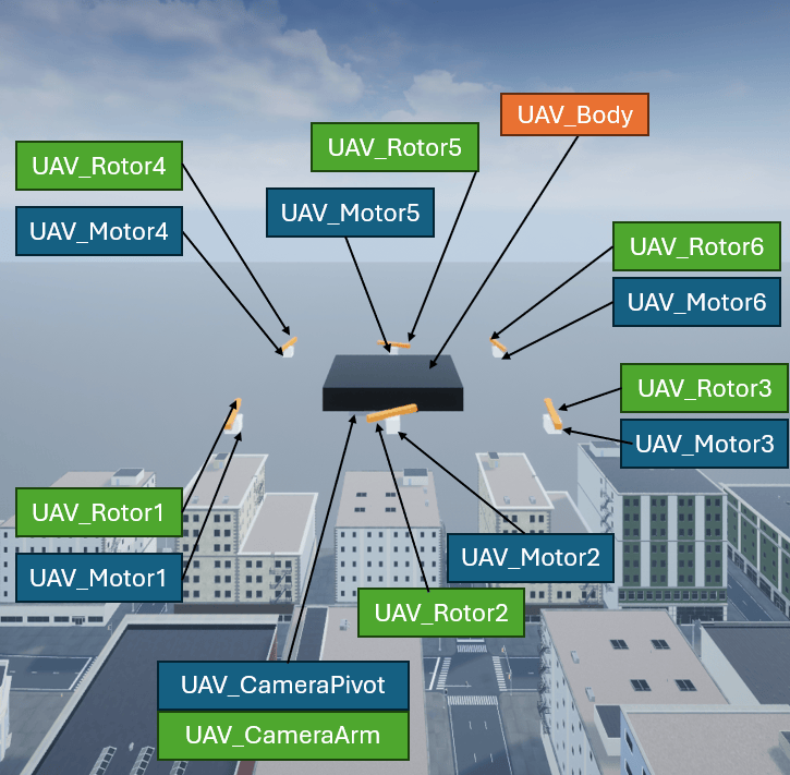
In this example, the Hexarotor UAV is configured with the following input:
UAV_Body rotation angle — 0 radian of roll, pitch, and yaw angles.
UAV_Motor1 tilt angle — 0 radian.
UAV_Rotor1 angular velocity — 250 RPM, clockwise.
UAV_Motor2 tilt angle — pi/2 radian, oscillating at a rate of 1 rad/s.
UAV_Rotor2 angular velocity — 60 RPM, clockwise.
UAV_Motor3 tilt angle — 0 radian.
UAV_Rotor3 angular velocity — 250 RPM, counter-clockwise.
UAV_Motor4 tilt angle — 0 radian.
UAV_Rotor4 angular velocity — 250 RPM, counter-clockwise.
UAV_Motor5 tilt angle — pi/2 radian, oscillating at a rate of 1 rad/s.
UAV_Rotor5 angular velocity — 60 RPM, counter-clockwise.
UAV_Motor6 tilt angle — 0 radian.
UAV_Rotor6 angular velocity — 250 RPM, clockwise.
Run the tiltRotorUAVModel.slx Simulink model to start the simulation.
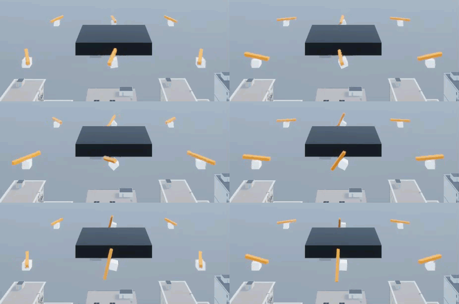
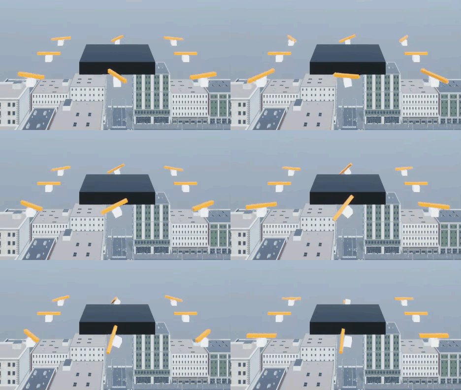
You can also run this example with an Octarotor UAV mesh by specifying the Path to custom mesh parameter of the Simulation 3D UAV Vehicle block as /MathWorksUAVContent/UAVs/OctaRotorUAV/OctaRotor.OctaRotor and running the model again.
Extended Examples
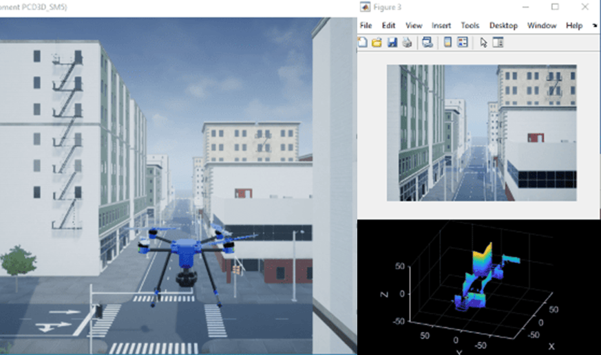
UAV Package Delivery
Simulate a small multicopter simulation taking off, flying, and landing in a city environment.
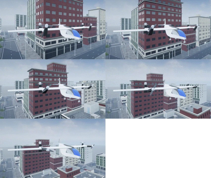
Visualize VTOL UAV Takeoff and Transition in 3D
Visualize a tilt-rotor VTOL UAV during vertical takeoff and forward transition using Unreal Engine.
Ports
Input
Translated position of the UAV, specified as a 1-by-3 vector
If Use geospatial coordinates for inputs and initial values parameter is disabled, specify the input as the X-, Y-, and Z-positions of the UAV in the Unreal Engine world coordinate frame. Units are in meters.
If Use geospatial coordinates for inputs and initial
values is enabled, specify the input as the latitude, longitude, and
altitude of the UAV in meters. The block places the UAV in Unreal Engine by evaluating
the translation relative to the GeoOrigin that you specified.
For more information on the coordinate systems, see Coordinate Systems for Unreal Engine Simulation in UAV Toolbox.
Data Types: double
Rotation of the UAV, specified as a 1-by-3 vector or a 17-by-3 matrix. You can
specify this input as a 1-by-3 vector for any value of the Type
parameter, but if Type is Custom, you can alternatively specify
Rotation as a 17-by-3 matrix.
1-by-3 vector
Contains the yaw, pitch, and roll angles of the UAV body, in radians. The UAV rotors rotate at a fixed angular velocity of 250 RPM (1500 deg/sec).
17-by-3 matrix
Tip
Use the Simulation 3D Custom UAV Pack block to generate translation and rotation inputs for
CustomUAV type with custom motor tilt angle and rotor angular velocity.For
Customtype, row 1 specifies the yaw, pitch, and roll of the UAV body. Rows 2, 4, 6, 8, 10, 12, 14, and 16 specify the rotation angles for motors 1 through 8. Rows 3, 5, 7, 9, 11, 13, 15, and 17 specify the angular velocities for rotors 1 through 8. For motor-rotor pairs not used, set the corresponding rows to zero.This table summarizes the rows of the rotation matrix.
Each angular velocity row contains the angular velocities around the X-, Y-, and Z- axes of the corresponding
UAV_RotorNmesh that you set up when exporting the mesh to Unreal Engine. Units are in revolutions per minute (RPM). The angular velocity sign convention follows the right-hand rule about each axis.Each rotation angles row contains the yaw, pitch, and roll angles of the corresponding UAV mesh part, in radians.
Matrix Row UAV Mesh Part 1 UAV_Bodyrotation angles2 UAV_Motor1rotation angles3 UAV_Rotor1angular velocities4 UAV_Motor2rotation angles5 UAV_Rotor2angular velocities6 UAV_Motor3rotation angles7 UAV_Rotor3angular velocities8 UAV_Motor4rotation angles9 UAV_Rotor4angular velocities10 UAV_Motor5rotation angles11 UAV_Rotor5angular velocities12 UAV_Motor6rotation angles13 UAV_Rotor6angular velocities14 UAV_Motor7rotation angles15 UAV_Rotor7angular velocities16 UAV_Motor8rotation angles17 UAV_Rotor8angular velocities
If you clear the Use geospatial coordinates for inputs and initial values parameter, the UAV body rotation angles are relative to the Unreal Engine world coordinate frame.
If you select the Use geospatial coordinates for inputs and initial values parameter, the UAV body rotation angles are relative to the local East-North-Up (ENU) frame at the current position of the UAV.
For more information on the coordinate systems, see Coordinate Systems for Unreal Engine Simulation in UAV Toolbox.
Data Types: double
Geospatial coordinates assigned to the origin point (0, 0, 0) of the Unreal Engine world coordinate frame, specified in the form [latitude longitude altitude]. Use this port to align the 3D simulation world with a real-world geographic location. latitude and longitude are in degrees, and altitude is in meters.
Dependencies
To enable this port, select the Use geospatial coordinates for inputs and initial values parameter.
Data Types: double
Parameters
Vehicle Parameters
Select the type of vehicle. To obtain the dimensions of each vehicle type, see these reference pages:
Quadcopter— QuadrotorFixed wing— Fixed Wing AircraftCustom— Custom UAV. Use this option for custom tilt-rotor UAVs with specified motor rotation angles and rotor angular velocities for up to eight motor-rotor pairs. For more details on custom UAV mesh, visit Prepare Custom UAV Vehicle Mesh for Unreal Engine Scenario Simulation
Reference path to the custom UAV mesh asset in your Unreal Engine project, specified as a character vector. The path must point to a static mesh asset in the Unreal Engine content browser. Add the mesh asset to the Unreal Engine project before running the simulation.
For steps to create and register a custom mesh asset, see Prepare Custom UAV Vehicle Mesh for Unreal Engine Scenario Simulation. For an example of how to obtain this path from the Unreal® editor, see Visualize VTOL UAV Mission over Urban Environment.
Dependencies
To enable this parameter, set the Type parameter to
Custom.
Select the visual color of the UAV mesh in the 3D scene. This parameter affects only the appearance of the vehicle and does not affect sensor outputs or simulation results.
Dependencies
To enable this parameter, set the Type parameter to
Quadcopter or Fixed
wing.
Name of vehicle. By default, when you use the block in your model, the block sets
the Name parameter to
SimulinkVehicle. The value of
X depends on the number of
Simulation 3D UAV Vehicle blocks that you have in your model.X
The vehicle name appears as a selection in the Parent name parameter of any UAV Toolbox Simulation 3D sensor blocks in the same model as the vehicle. With the Parent name parameter, you can select the vehicle on which to mount the sensor.
Select this parameter to use geospatial coordinates for port inputs and initial values. When enabled:
The
Translationinput accepts [latitude, longitude, altitude] instead of [X, Y, Z].The
GeoOrigininput port becomes active and accepts the [latitude, longitude, altitude] of the Unreal Engine world origin.Set Initial Georeference Origin (LLA) to match the geographic location of your simulation scene.
The block places the UAV relative to the GeoOrigin position.
Initial Values
Specify the initial position of your vehicle in one of these forms:
[X Y Z] when you clear the Use geospatial coordinates for inputs and initial values parameter. X, Y, and Z are the translation along the X-axis, Y-axis, and Z-axis, respectively, in the inertial Z-down coordinate system, in meters.
[latitude longitude altitude] when you enable the Use geospatial coordinates for inputs and initial values parameter. You must specify latitude and longitude in degrees, and altitude in meters.
Specify the initial georeference origin in the form [latitude longitude altitude]. You must specify latitude and longitude in degrees, and altitude in meters.
Dependencies
To enable this parameter, select the Use geospatial coordinates for inputs and initial values parameter.
Initial rotation of the UAV. The dimensions of this parameter depend on the value
of the Type parameter. You can specify this parameter as a 1-by-3
vector for any value of the Type parameter, but if Type is
Custom, you can alternatively specify this parameter as a 17-by-3
matrix.
See the Rotation input for details on specifying this value.
Sample Time
Sample time, Ts, specified as a positive scalar in seconds. The graphics frame rate is the inverse of the sample time.
If you set the sample time to -1, the block uses the sample
time specified in the Simulation 3D Scene Configuration block.
Version History
Introduced in R2020bThe Simulation 3D UAV Vehicle block now accepts a 17-by-3 matrix for the rotation input when you set
the Type parameter to Custom.
The first row specifies the rotation angles of the UAV body. After that, each even row specifies the rotation angles for UAV motors 1 through 8, while each odd row specifies the angular velocities for the corresponding rotor.
Simulating models with the Simulation 3D UAV Vehicle block requires Simulink 3D Animation.
You can select the Use geospatial coordinates for inputs and initial values parameter to specify inputs and initial values using geospatial coordinates.
See Also
Blocks
Tools
MATLAB Command
You clicked a link that corresponds to this MATLAB command:
Run the command by entering it in the MATLAB Command Window. Web browsers do not support MATLAB commands.
选择网站
选择网站以获取翻译的可用内容,以及查看当地活动和优惠。根据您的位置,我们建议您选择:。
您也可以从以下列表中选择网站:
如何获得最佳网站性能
选择中国网站(中文或英文)以获得最佳网站性能。其他 MathWorks 国家/地区网站并未针对您所在位置的访问进行优化。
美洲
- América Latina (Español)
- Canada (English)
- United States (English)
欧洲
- Belgium (English)
- Denmark (English)
- Deutschland (Deutsch)
- España (Español)
- Finland (English)
- France (Français)
- Ireland (English)
- Italia (Italiano)
- Luxembourg (English)
- Netherlands (English)
- Norway (English)
- Österreich (Deutsch)
- Portugal (English)
- Sweden (English)
- Switzerland
- United Kingdom (English)

