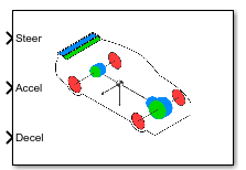
Simulation 3D Physics Vehicle
Libraries:
Vehicle Dynamics Blockset /
Vehicle Scenarios /
Sim3D /
Sim3D Vehicle /
Components
Description
Note
Simulating models with the Simulation 3D Physics Vehicle block requires Simulink® 3D Animation™.
The Simulation 3D Physics Vehicle block implements a controllable 10DOF vehicle in the 3D simulation environment, with a vertical DOF for each wheel and 6DOF for the chassis.
To use the Simulation 3D Physics Vehicle block, ensure that the
Simulation 3D Scene Configuration block is in your model. If you set the
Sample time parameter of the Simulation 3D Physics Vehicle block to
-1, the block uses the sample time specified in the Simulation 3D
Scene Configuration block.
The block input uses the vehicle Z-down right-handed (RH) Cartesian coordinate system defined in SAE J670[1]. The coordinate system is inertial and initially aligned with the vehicle geometric center:
X-axis — Along vehicle longitudinal axis, points forward
Y-axis — Along vehicle lateral axis, points to the right
Z-axis — Points downward
Tip
Verify that the Simulation 3D Scene
Configuration block executes before the Simulation 3D Physics
Vehicle block. With this sequence, the Unreal Engine® 3D visualization environment prepares the data before the Simulation 3D
Physics Vehicle block receives the data. To check the block execution order,
right-click the blocks and then click the Properties button ![]() . On the General tab, confirm these
Priority settings:
. On the General tab, confirm these
Priority settings:
Simulation 3D Scene Configuration —
0Simulation 3D Physics Vehicle —
-1
For more information about execution order, see Control and Display Execution Order.
Examples
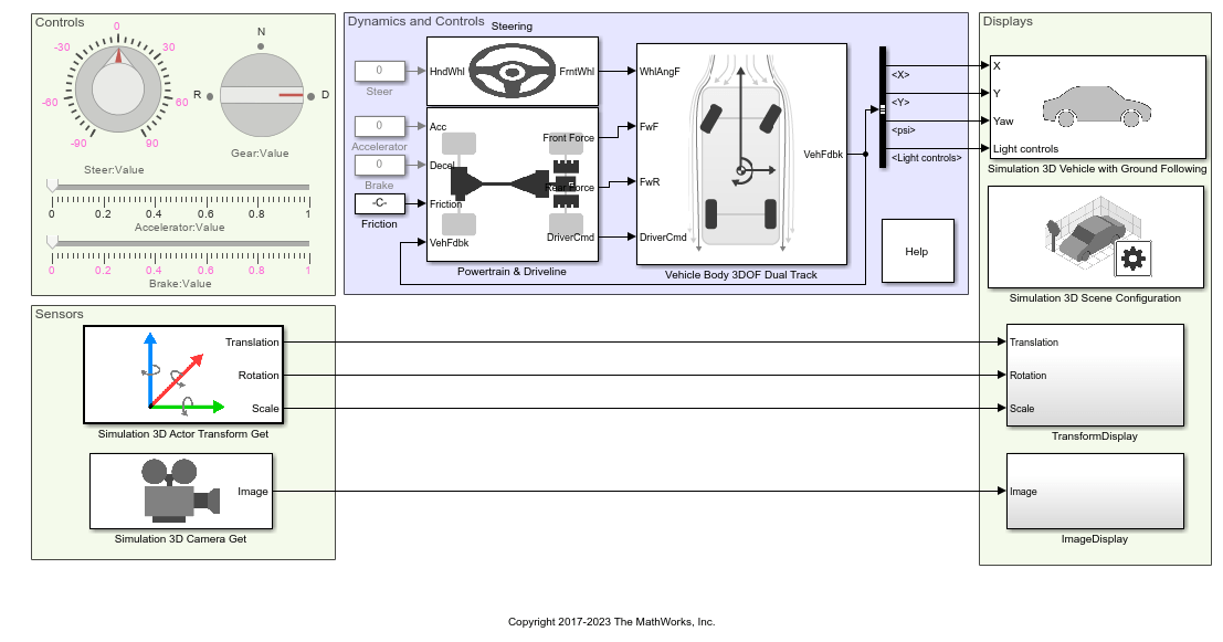
Scene Interrogation with Camera and Ray Tracing Reference Application
Interrogate a 3D Unreal Engine scene with a vehicle dynamics model by using a camera and ray tracing reference application project.
Ports
Input
Normalized steer angle, specified as a scalar. SteerCmd corresponds to the minimum and maximum range of the steering angle as determined by the Front wheel max steer angle and Rear wheel max steer angle parameters, respectively.
Normalized acceleration torque request to the vehicle powertrain, specified as a scalar. The exact response is characterized by the engine, transmission, and other vehicle parameters.
Normalized deceleration torque request to the vehicle braking system, specified as a scalar. The exact braking response is characterized by the engine, transmission and other vehicle parameters.
Gear input, specified as either 1, -1, or
0.
1– Forward shift gear-1– Reverse gear0– Neutral gear
If you select manual shift mode, then the vehicle shifts according to the signal, but the values listed still apply. Any input set that does not correspond to a valid gear is ignored.
Output
This port is optional.
Bus signal containing these block values.
| Signal | Description | Value | Units | |||||
|---|---|---|---|---|---|---|---|---|
InertFrm | Cg | Disp | X | Vehicle CG displacement along the earth-fixed X-axis | Computed | m | ||
Y | Vehicle CG displacement along the earth-fixed Y-axis | Computed | m | |||||
Z | Vehicle CG displacement along the earth-fixed Z-axis | 0 | m | |||||
Vel | Xdot | Vehicle CG velocity along the earth-fixed X-axis | Computed | m/s | ||||
Ydot | Vehicle CG velocity along the earth-fixed Y-axis | Computed | m/s | |||||
Zdot | Vehicle CG velocity along the earth-fixed Z-axis | 0 | m/s | |||||
Ang | phi | Rotation of the vehicle-fixed frame about the earth-fixed X-axis (roll) | 0 | rad | ||||
theta | Rotation of the vehicle-fixed frame about the earth-fixed Y-axis (pitch) | 0 | rad | |||||
psi | Rotation of the vehicle-fixed frame about the earth-fixed Z-axis (yaw) | Computed | rad | |||||
BdyFrm | Cg | Vel | xdot | Vehicle CG velocity along the vehicle-fixed x-axis | Computed | m/s | ||
ydot | Vehicle CG velocity along the vehicle-fixed y-axis | Computed | m/s | |||||
zdot | Vehicle CG velocity along the vehicle-fixed z-axis | 0 | m/s | |||||
Ang | Beta | Body slip angle, β
| Computed | rad | ||||
AngVel | p | Vehicle angular velocity about the vehicle-fixed x-axis (roll rate) | 0 | rad/s | ||||
q | Vehicle angular velocity about the vehicle-fixed y-axis (pitch rate) | 0 | rad/s | |||||
r | Vehicle angular velocity about the vehicle-fixed z-axis (yaw rate) | Computed | rad/s | |||||
Acc | ax | Vehicle CG acceleration along the vehicle-fixed x-axis | Computed | gn | ||||
ay | Vehicle CG acceleration along the vehicle-fixed y-axis | Computed | gn | |||||
az | Vehicle CG acceleration along the vehicle-fixed z-axis | 0 | gn | |||||
xddot | Vehicle CG acceleration along the vehicle-fixed x-axis | Computed | m/s^2 | |||||
yddot | Vehicle CG acceleration along the vehicle-fixed y-axis | Computed | m/s^2 | |||||
zddot | Vehicle CG acceleration along the vehicle-fixed z-axis | 0 | m/s^2 | |||||
AngAcc | pdot | Vehicle angular acceleration about the vehicle-fixed x-axis | 0 | rad/s | ||||
qdot | Vehicle angular acceleration about the vehicle-fixed y-axis | 0 | rad/s | |||||
rdot | Vehicle angular acceleration about the vehicle-fixed z-axis | Computed | rad/s | |||||
DCM | Direction cosine matrix | Computed | rad | |||||
Forces | Tires | FrntTires | Lft | Fx | Front left tire force along the vehicle-fixed x-axis | Estimated | N | |
Fy | Front left tire force along the vehicle-fixed y-axis | Estimated | N | |||||
Fz | Front left tire force along the vehicle-fixed z-axis | Estimated | N | |||||
Rght | Fx | Front right tire force along the vehicle-fixed x-axis | Estimated | N | ||||
Fy | Front right tire force along the vehicle-fixed y-axis | Estimated | N | |||||
Fz | Front right tire force along the vehicle-fixed z-axis | Estimated | N | |||||
RearTires | Lft | Fx | Rear left tire force along the vehicle-fixed x-axis | Estimated | N | |||
Fy | Rear left tire force along the vehicle-fixed y-axis | Estimated | N | |||||
Fz | Rear left tire force along the vehicle-fixed z-axis | Estimated | N | |||||
Rght | Fx | Rear right tire force along the vehicle-fixed x-axis | Estimated | N | ||||
Fy | Rear right tire force along the vehicle-fixed y-axis | Estimated | N | |||||
Note
Tire forces are no longer explicitly available from Unreal Engine as a result of Epic Games® transition from PhysX® to Chaos Physics. The values calculated for the tire forces are approximate estimates.
| Signal | Description | Variable | Units | |
|---|---|---|---|---|
Mtr | MtrSpd | Applied drive shaft angular speed input | ωi | RPM |
Trans | TransGearCmd | Commanded gear | Ncmd | N/A |
TransGear | Engaged gear | N | N/A | |
Vehicle CG velocity along the vehicle-fixed x-axis, in m/s.
Vehicle CG velocity along the vehicle-fixed y-axis, in m/s.
Rotation of the vehicle-fixed frame about the earth-fixed Z-axis (yaw), in rad.
Vehicle angular velocity, r, about the vehicle-fixed
z-axis (yaw rate), in rad/s.
Parameters
Chassis
Specify the vehicle type. This table provides links to the vehicle dimensions.
| Vehicle type Setting | Vehicle Dimensions |
|---|---|
Muscle car | |
Sedan | |
Sport utility vehicle | |
Small pickup truck | |
Hatchback | |
Box truck | |
Formula student vehicle |
Dependencies
Selecting Custom enables parameters that allow you to import a
custom mesh for your vehicle.
Programmatic Use
To set the block parameter value
programmatically, use the set_param function.
To get the block parameter value
programmatically, use the get_param function.
| Parameter: | PassVehMesh |
| Values: | Muscle car (default) | Sedan | Sport utility vehicle | Small pickup truck | Hatchback | Box Truck | Formula student vehicle | Custom |
| Data Types: | character vector |
Select the color of the vehicle.
Programmatic Use
To set the block parameter value
programmatically, use the set_param function.
To get the block parameter value
programmatically, use the get_param function.
| Parameter: | VehColor |
| Values: | Red (default) | Orange | Yellow | Green | Blue | Black | White | Silver | Dazzle camouflage |
| Data Types: | character vector |
By default, when you use this block in your model, the block sets the
Name parameter to
SimulinkVehicle. The value of
XX
Programmatic Use
To set the block parameter value
programmatically, use the set_param function.
To get the block parameter value
programmatically, use the get_param function.
| Parameter: | ActorName |
| Values: | SimulinkVehicle1 (default) | character vector |
| Data Types: | character vector |
Initial vehicle position, specified as a 1-by-3 array, in m. Array elements are values along the Coordinate system parameter X-, Y-, and Z- axes, respectively.
Programmatic Use
To set the block parameter value
programmatically, use the set_param function.
To get the block parameter value
programmatically, use the get_param function.
| Parameter: | InitialPos |
| Values: | [0, 0, -0.5] (default) | 1-by-3 array |
| Data Types: | double |
Initial vehicle rotation, specified as a 1-by-3 array, in rad. Array elements are values about the Coordinate system parameter X-, Y-, and Z-axes, respectively.
Programmatic Use
To set the block parameter value
programmatically, use the set_param function.
To get the block parameter value
programmatically, use the get_param function.
| Parameter: | InitialRot |
| Values: | [0, 0, 0] (default) | 1-by-3 array |
| Data Types: | double |
Vehicle mass, in kg. This value does not include the wheel masses.
Programmatic Use
To set the block parameter value
programmatically, use the set_param function.
To get the block parameter value
programmatically, use the get_param function.
| Parameter: | Mass |
| Values: | 1500 (default) | scalar |
| Data Types: | double |
Offset in center of mass, specified as a three-element vector, in meters.
Programmatic Use
To set the block parameter value
programmatically, use the set_param function.
To get the block parameter value
programmatically, use the get_param function.
| Parameter: | CgOffset |
| Values: | [ 0, 0, 0] (default) | vector |
| Data Types: | double |
Scaling of inertia tensor, specified as a three-element dimensionless vector.
Programmatic Use
To set the block parameter value
programmatically, use the set_param function.
To get the block parameter value
programmatically, use the get_param function.
| Parameter: | IvehScale |
| Values: | [1, 1, 1] (default) | vector |
| Data Types: | double |
Height of chassis used to calculate drag force, specified in meters.
Programmatic Use
To set the block parameter value
programmatically, use the set_param function.
To get the block parameter value
programmatically, use the get_param function.
| Parameter: | ChassisHeight |
| Values: | 1.0 (default) | scalar |
| Data Types: | double |
Path to custom mesh file.
Dependencies
To enable this parameter, set Type to
Custom.
Programmatic Use
To set the block parameter value
programmatically, use the set_param function.
To get the block parameter value
programmatically, use the get_param function.
| Parameter: | MeshPath |
| Values: | /MathWorksSimulation/Vehicles/Muscle/Meshes/SK_MuscleCar.SK_Sedan (default) | valid path |
| Data Types: | character vector |
The vehicle track width refers to the distance between the wheels, or the axle length, specified in meters.
Dependencies
To enable this parameter, set Type to
Custom.
Programmatic Use
To set the block parameter value
programmatically, use the set_param function.
To get the block parameter value
programmatically, use the get_param function.
| Parameter: | TrackWidth |
| Values: | 1.9 (default) | scalar |
| Data Types: | double |
Wheel base, in meters.
Dependencies
To enable this parameter, set Type to
Custom.
Programmatic Use
To set the block parameter value
programmatically, use the set_param function.
To get the block parameter value
programmatically, use the get_param function.
| Parameter: | WheelBase |
| Values: | 3 (default) | scalar |
| Data Types: | double |
Front wheel radius, in meters.
Dependencies
To enable this parameter, set Type to
Custom.
Programmatic Use
To set the block parameter value
programmatically, use the set_param function.
To get the block parameter value
programmatically, use the get_param function.
| Parameter: | FrntWhlRadius |
| Values: | 0.23 (default) | scalar |
| Data Types: | double |
Front wheel width, in meters.
Dependencies
To enable this parameter, set Type to
Custom.
Programmatic Use
To set the block parameter value
programmatically, use the set_param function.
To get the block parameter value
programmatically, use the get_param function.
| Parameter: | FrntWhlWidth |
| Values: | 0.20 (default) | scalar |
| Data Types: | double |
Rear wheel radius, in meters.
Dependencies
To enable this parameter, set Type to
Custom.
Programmatic Use
To set the block parameter value
programmatically, use the set_param function.
To get the block parameter value
programmatically, use the get_param function.
| Parameter: | RearWhlRadius |
| Values: | 0.23 (default) | scalar |
| Data Types: | double |
Rear wheel width, in meters.
Dependencies
To enable this parameter, set Type to
Custom.
Programmatic Use
To set the block parameter value
programmatically, use the set_param function.
To get the block parameter value
programmatically, use the get_param function.
| Parameter: | RearWhlWidth |
| Values: | 0.20 (default) | scalar |
| Data Types: | double |
Powertrain and Driveline
Powertrain
Motor torque indices, in N·m. You can use these pre-transmission values to represent either an electric motor or a conventional engine.
Programmatic Use
To set the block parameter value
programmatically, use the set_param function.
To get the block parameter value
programmatically, use the get_param function.
| Parameter: | TrqCrv |
| Values: | [ 75, 75, 97, 117, 152, 175, 175, 175, 175, 165,
155, 145, 140, 135, 125, 115, 50 ] (default) | vector |
| Data Types: | double |
Motor speed breakpoints, in rpm.
Programmatic Use
To set the block parameter value
programmatically, use the set_param function.
To get the block parameter value
programmatically, use the get_param function.
| Parameter: | SpdCrv |
| Values: | [ 0, 750, 1054, 1357, 1660, 1964, 2267, 2571, 2875,
3178, 3482, 3785, 4089, 4393, 4696, 5000, 7000 ] (default) | vector |
| Data Types: | double |
Max powertrain speed, in rpm. If you select an automatic transmission option, this value also corresponds to the normalized shift points used in the upshift and downshift logic.
Programmatic Use
To set the block parameter value
programmatically, use the set_param function.
To get the block parameter value
programmatically, use the get_param function.
| Parameter: | MaxRPM |
| Values: | 7000 (default) | scalar |
| Data Types: | double |
Powertrain damping at zero torque request in gear, in kg·m2/s.
Programmatic Use
To set the block parameter value
programmatically, use the set_param function.
To get the block parameter value
programmatically, use the get_param function.
| Parameter: | bEngMin |
| Values: | 2 (default) | scalar |
| Data Types: | double |
Driveline
Implement rear wheel, front wheel, or all wheel drive.
Programmatic Use
To set the block parameter value
programmatically, use the set_param function.
To get the block parameter value
programmatically, use the get_param function.
| Parameter: | DrivetrainType |
| Values: | Rear Wheel Drive (default) | Front Wheel Drive | All Wheel Drive |
| Data Types: | character vector |
Front to rear torque split ratio, dimensionless.
1 indicates 100% torque to the front. 0
indicates 100% to the rear.
Dependencies
To enable this parameter, set Drivetrain type to
All Wheel Drive.
Programmatic Use
To set the block parameter value
programmatically, use the set_param function.
To get the block parameter value
programmatically, use the get_param function.
| Parameter: | FrontRearSplit |
| Values: | 0.5 (default) | scalar |
| Data Types: | double |
Implement an automatic or manual transmission.
Note
You must provide a GearCmd input even if
Transmission type is set to
Automatic.
Programmatic Use
To set the block parameter value
programmatically, use the set_param function.
To get the block parameter value
programmatically, use the get_param function.
| Parameter: | TransType |
| Values: | Automatic (default) | Manual |
| Data Types: | character vector |
Gear ratios, dimensionless.
Note
You must provide at least one negative ratio for reverse gear. You must also provide a neutral ratio where the length of the array corresponds to the number of forward gears plus two, one for reverse and one for neutral.
Programmatic Use
To set the block parameter value
programmatically, use the set_param function.
To get the block parameter value
programmatically, use the get_param function.
| Parameter: | N |
| Values: | [ -3.5, 1, 4.75, 3.75, 3.25, 2.75, 2.25, 1.5, 1,
0.75 ] (default) | vector |
| Data Types: | double |
Time taken to complete a shift, specified as a scalar, in s.
Programmatic Use
To set the block parameter value
programmatically, use the set_param function.
To get the block parameter value
programmatically, use the get_param function.
| Parameter: | tShift |
| Values: | 0.1 (default) | scalar |
| Data Types: | double |
Final drive ratio, dimensionless. This value is the post transmission ratio, typically found in a differential or final drive gearbox.
Programmatic Use
To set the block parameter value
programmatically, use the set_param function.
To get the block parameter value
programmatically, use the get_param function.
| Parameter: | Ndiff |
| Values: | 3.2 (default) | scalar |
| Data Types: | double |
Steering and Brakes
Steering
Steering type, specified as Ackermann or
Linear.
Programmatic Use
To set the block parameter value
programmatically, use the set_param function.
To get the block parameter value
programmatically, use the get_param function.
| Parameter: | SteerType |
| Values: | Ackermann (default) | Linear |
| Data Types: | character vector |
Outside to inside steer angle ratio, dimensionless.
Dependencies
To enable this parameter, set Steering type to
Linear.
Programmatic Use
To set the block parameter value
programmatically, use the set_param function.
To get the block parameter value
programmatically, use the get_param function.
| Parameter: | SteerAngleRatio |
| Values: | 1.0 (default) | scalar |
| Data Types: | double |
Front wheel max steer angle, in radians. This value is the absolute angle which
the front wheels turn with a -1 or 1 steer
command input signal.
Programmatic Use
To set the block parameter value
programmatically, use the set_param function.
To get the block parameter value
programmatically, use the get_param function.
| Parameter: | FrntWhlMaxSteer |
| Values: | 45*pi/180 (default) | scalar |
| Data Types: | double |
Rear wheel max steer angle, in radians. This value is the absolute angle which the
rear wheels turn with a -1 or 1 steer command
input signal.
Programmatic Use
To set the block parameter value
programmatically, use the set_param function.
To get the block parameter value
programmatically, use the get_param function.
| Parameter: | RearWhlMaxSteer |
| Values: | 0 (default) | scalar |
| Data Types: | double |
Maximum steering ratio breakpoints, dimensionless. This value is the gain by which the steering command is affected by the vehicle speed brake points.
Programmatic Use
To set the block parameter value
programmatically, use the set_param function.
To get the block parameter value
programmatically, use the get_param function.
| Parameter: | SteerSpdFctTbl |
| Values: | [1, 0.8, 0.7] (default) | vector |
| Data Types: | double |
Steering ratio speed breakpoints, in m/s. This value is the vehicle forward speed break points used by the steer ratio gains.
Programmatic Use
To set the block parameter value
programmatically, use the set_param function.
To get the block parameter value
programmatically, use the get_param function.
| Parameter: | SteerVehSpdBpts |
| Values: | [0, 60, 120]./3.6 (default) | vector |
| Data Types: | double |
Brakes
Maximum front wheel torque, in N·m. This value is the maximum braking torque applied to the front wheels corresponding to the normalized DecelCmd input.
Programmatic Use
To set the block parameter value
programmatically, use the set_param function.
To get the block parameter value
programmatically, use the get_param function.
| Parameter: | FrntWhlMaxTrq |
| Values: | 1500 (default) | scalar |
| Data Types: | double |
Maximum rear wheel torque, in N·m. This value is the maximum braking torque applied to the rear wheels corresponding to the normalized DecelCmd input.
Programmatic Use
To set the block parameter value
programmatically, use the set_param function.
To get the block parameter value
programmatically, use the get_param function.
| Parameter: | RearWhlMaxTrq |
| Values: | 1500 (default) | scalar |
| Data Types: | double |
Select this parameter to enable handbrake input.
Programmatic Use
To set the block parameter value
programmatically, use the set_param function.
To get the block parameter value
programmatically, use the get_param function.
| Parameter: | HndBrkEnable |
| Values: | off (default) | on |
| Data Types: | character vector |
Enable this parameter to have the handbrake affect the front wheels.
Dependencies
To enable this parameter, select Enable handbrake input.
Programmatic Use
To set the block parameter value
programmatically, use the set_param function.
To get the block parameter value
programmatically, use the get_param function.
| Parameter: | FrntWhlHndBrkEnable |
| Values: | off (default) | on |
| Data Types: | character vector |
Enable this parameter to have the handbrake affect the rear wheels.
Dependencies
To enable this parameter, select Enable handbrake input.
Programmatic Use
To set the block parameter value
programmatically, use the set_param function.
To get the block parameter value
programmatically, use the get_param function.
| Parameter: | RearWhlHndBrkEnable |
| Values: | off (default) | on |
| Data Types: | character vector |
Maximum front wheel hand brake torque, in Nm.
Dependencies
To enable this parameter, select Front wheels affected by handbrake.
Programmatic Use
To set the block parameter value
programmatically, use the set_param function.
To get the block parameter value
programmatically, use the get_param function.
| Parameter: | FrntWhlMaxHndBrkTrq |
| Values: | 3000 (default) | scalar |
| Data Types: | double |
Maximum rear wheel hand brake torque, in Nm.
Dependencies
To enable this parameter, select Front wheels affected by handbrake.
Programmatic Use
To set the block parameter value
programmatically, use the set_param function.
To get the block parameter value
programmatically, use the get_param function.
| Parameter: | RearWhlMaxHndBrkTrq |
| Values: | 3000 (default) | scalar |
| Data Types: | double |
Suspension, Wheels and Tires
Suspension
Front suspension force offset, specified as a three-element vector, in meters.
Programmatic Use
To set the block parameter value
programmatically, use the set_param function.
To get the block parameter value
programmatically, use the get_param function.
| Parameter: | FrntSuspFOffset |
| Values: | [0,0,0] (default) | vector |
| Data Types: | double |
Maximum front suspension compression or jounce, specified as a scalar, in meters. Jounce is the upward movement or compression of suspension components.
Programmatic Use
To set the block parameter value
programmatically, use the set_param function.
To get the block parameter value
programmatically, use the get_param function.
| Parameter: | FrntSuspMaxComp |
| Values: | 0.15 (default) | scalar |
| Data Types: | double |
Maximum front suspension extension or rebound, specified as a scalar in meters. Rebound is the downward movement or extension of suspension components.
Programmatic Use
To set the block parameter value
programmatically, use the set_param function.
To get the block parameter value
programmatically, use the get_param function.
| Parameter: | FrntSuspMaxExt |
| Values: | 0.1 (default) | scalar |
| Data Types: | double |
Damping ratio of front suspension, dimensionless. Damping ratio is the coefficient of the damper at its peak level, where the vehicle is in a completely stable state.
Programmatic Use
To set the block parameter value
programmatically, use the set_param function.
To get the block parameter value
programmatically, use the get_param function.
| Parameter: | FrntSuspDamping |
| Values: | 0.5 (default) | scalar |
| Data Types: | double |
Rear suspension force offset, specified as a three-element vector, in meters.
Programmatic Use
To set the block parameter value
programmatically, use the set_param function.
To get the block parameter value
programmatically, use the get_param function.
| Parameter: | RearSuspFOffset |
| Values: | [0,0,0] (default) | vector |
| Data Types: | double |
Maximum rear suspension compression or jounce, specified as a scalar, in meters. Jounce is the upward movement or compression of suspension components.
Programmatic Use
To set the block parameter value
programmatically, use the set_param function.
To get the block parameter value
programmatically, use the get_param function.
| Parameter: | RearSuspMaxComp |
| Values: | 0.15 (default) | scalar |
| Data Types: | double |
Maximum rear suspension extension or rebound, specified as a scalar, in meters. Rebound is the downward movement or extension of suspension components.
Programmatic Use
To set the block parameter value
programmatically, use the set_param function.
To get the block parameter value
programmatically, use the get_param function.
| Parameter: | RearSuspMaxExt |
| Values: | 0.1 (default) | scalar |
| Data Types: | double |
Damping ratio of rear suspension, dimensionless. Damping ratio is the coefficient of the damper at its peak level, where the vehicle is in a completely stable state.
Programmatic Use
To set the block parameter value
programmatically, use the set_param function.
To get the block parameter value
programmatically, use the get_param function.
| Parameter: | RearSuspDamping |
| Values: | 0.5 (default) | scalar |
| Data Types: | double |
Wheels
Select this parameter to enable anti-lock braking.
Programmatic Use
To set the block parameter value
programmatically, use the set_param function.
To get the block parameter value
programmatically, use the get_param function.
| Parameter: | ABSEnable |
| Values: | Off (default) | On |
| Data Types: | character vector |
Tires
Light Controls
Select whether to control the vehicle headlights. Use the enabled parameters to set the light parameters, including headlight intensity.
Dependencies
Selecting this parameter:
Creates the input port
Light controls.Enables these light parameters.
Lights Light Parameters Headlights Headlight color
High beam intensity
Low beam intensity
High beam cone half angle
Low beam cone half angle
Left headlight beam orientation
Right headlight beam orientation
Brake lights Brake light intensity
Reverse lights Reverse light intensity
Turn signal lights Turn signal light intensity
Period
Pulse width
Programmatic Use
To set the block parameter
value programmatically, use the set_param
function.
To get the block parameter
value programmatically, use the get_param function.
| Parameter: | VehLightsControl |
| Values: | Off (default) | On |
| Data Types: | character vector |
Headlights
Headlight color, specified as a normalized 1-by-3 vector of RGB triplet values.
Dependencies
To enable this parameter, select Enable light controls.
Programmatic Use
To set the block parameter
value programmatically, use the set_param
function.
To get the block parameter
value programmatically, use the get_param function.
| Parameter: | HeadlightColor |
| Values: | [1,1,1] (default) | vector |
| Data Types: | double |
High beam intensity, in cd.
Dependencies
To enable this parameter, select Enable light controls.
Programmatic Use
To set the block parameter
value programmatically, use the set_param
function.
To get the block parameter
value programmatically, use the get_param function.
| Parameter: | HighBeamIntensity |
| Values: | 100000 (default) | scalar |
| Data Types: | double |
Low beam intensity, in cd.
Dependencies
To enable this parameter, select Enable light controls.
Programmatic Use
To set the block parameter
value programmatically, use the set_param
function.
To get the block parameter
value programmatically, use the get_param function.
| Parameter: | LowBeamIntensity |
| Values: | 60000 (default) | scalar |
| Data Types: | double |
High beam cone half angle, in rad.
Dependencies
To enable this parameter, select Enable light controls.
Programmatic Use
To set the block parameter
value programmatically, use the set_param
function.
To get the block parameter
value programmatically, use the get_param function.
| Parameter: | HighBeamConeAngle |
| Values: | 1.22 (default) | scalar |
| Data Types: | double |
Low beam cone half angle, in rad.
Dependencies
To enable this parameter, select Enable light controls.
Programmatic Use
To set the block parameter
value programmatically, use the set_param
function.
To get the block parameter
value programmatically, use the get_param function.
| Parameter: | LowBeamConeAngle |
| Values: | 1.22 (default) | scalar |
| Data Types: | double |
Pitch and yaw orientation of the left headlight beam orientation in the
Z-down coordinate system, specified as a 1-by-2 vector,
in rad. The first element of the vector, [1,1], is the pitch
angle. The second element of the vector, [1,2], is the yaw
angle.
Dependencies
To enable this parameter, select Enable light controls.
Programmatic Use
To set the block parameter
value programmatically, use the set_param
function.
To get the block parameter
value programmatically, use the get_param function.
| Parameter: | LeftHeadlightOrientation |
| Values: | [0,0] (default) | vector |
| Data Types: | double |
Pitch and yaw orientation of the right headlight beam orientation in the
Z-down coordinate system, specified as a 1-by-2 vector,
in rad. The first element of the vector, [1,1], is the pitch
angle. The second element of the vector, [1,2], is the yaw
angle.
Dependencies
To enable this parameter, select Enable light controls.
Programmatic Use
To set the block parameter
value programmatically, use the set_param
function.
To get the block parameter
value programmatically, use the get_param function.
| Parameter: | RightHeadlightOrientation |
| Values: | [0,0] (default) | vector |
| Data Types: | double |
Brake Lights
Brake light intensity, in cd/m^2.
Dependencies
To enable this parameter, select Enable light controls.
Programmatic Use
To set the block parameter
value programmatically, use the set_param
function.
To get the block parameter
value programmatically, use the get_param function.
| Parameter: | BrakelightIntensity |
| Values: | 500 (default) | scalar |
| Data Types: | double |
Reverse Lights
Reverse light intensity, in cd/m^2.
Dependencies
To enable this parameter, select Enable light controls.
Programmatic Use
To set the block parameter
value programmatically, use the set_param
function.
To get the block parameter
value programmatically, use the get_param function.
| Parameter: | ReverselightIntensity |
| Values: | 500 (default) | scalar |
| Data Types: | double |
Turn Signal Lights
Turn signal light intensity, in cd/m^2.
Dependencies
To enable this parameter, select Enable light controls.
Programmatic Use
To set the block parameter
value programmatically, use the set_param
function.
To get the block parameter
value programmatically, use the get_param function.
| Parameter: | SignallightIntensity |
| Values: | 500 (default) | scalar |
| Data Types: | double |
Turn signal light period, in s.
Dependencies
To enable this parameter, select Enable light controls.
Programmatic Use
To set the block parameter
value programmatically, use the set_param
function.
To get the block parameter
value programmatically, use the get_param function.
| Parameter: | SignallightPeriod |
| Values: | 1 (default) | scalar |
| Data Types: | double |
Turn signal light pulse width, specified as a percent of the period.
Dependencies
To enable this parameter, select Enable light controls.
Programmatic Use
To set the block parameter
value programmatically, use the set_param
function.
To get the block parameter
value programmatically, use the get_param function.
| Parameter: | SignalPulseWidth |
| Values: | 50 (default) | scalar |
| Data Types: | double |
Sample Time
Sample time, Ts. The graphics frame rate is the inverse of the sample time.
Programmatic Use
To set the block parameter value
programmatically, use the set_param function.
To get the block parameter value
programmatically, use the get_param function.
| Parameter: | SampleTime |
| Values: | -1 (default) | scalar |
| Data Types: | double |
Ground Truth
Select this parameter to return location and orientation.
Programmatic Use
To set the block parameter value
programmatically, use the set_param function.
To get the block parameter value
programmatically, use the get_param function.
| Parameter: | StandardOutportEnabled |
| Values: | off (default) | on |
| Data Types: | character vector |
Select this parameter to return nominal vehicle state feedback.
Programmatic Use
To set the block parameter value
programmatically, use the set_param function.
To get the block parameter value
programmatically, use the get_param function.
| Parameter: | TransformOutportEnabled |
| Values: | off (default) | on |
| Data Types: | character vector |
References
[1] Vehicle Dynamics Standards Committee. Vehicle Dynamics Terminology. SAE J670. Warrendale, PA: Society of Automotive Engineers, 2008.
[2] Technical Committee. Road Vehicles — Vehicle Dynamics and Road-Holding Ability — Vocabulary. ISO 8855:2011. Geneva, Switzerland: International Organization for Standardization, 2011.
Version History
Introduced in R2022bStarting in R2024b, you can specify Color, VehColor as
Dazzle Camouflage for the Simulation 3D Physics
Vehicle block.
Simulating models with the Simulation 3D Physics Vehicle block requires Simulink 3D Animation.
Starting in R2024a, the Unreal Engine version that ships with Simulink 3D Animation uses Chaos Physics instead of the PhysX physics engine. As a result of this change, a number of parameters have been removed and added.
This table lists the parameters that have been removed.
| Vehicle Element | Removed Parameter |
|---|---|
Powertrain | Powertrain damping at zero torque request, in neutral |
Driveline | Shift down indices |
Shift up indices | |
Clutch slip torque | |
Minimum shift latency | |
Steering | Percent Ackermann |
Suspension | Front suspension natural frequency |
Rear suspension natural frequency | |
Wheels | Front wheel mass |
Rear wheel mass | |
Front wheel damping | |
Rear wheel damping | |
Tires | Front tire lateral stiffness |
Rear tire lateral stiffness | |
Front tire longitudinal stiffness | |
Rear tire longitudinal stiffness | |
Front tire max lateral stiffness factor | |
Rear tire max lateral stiffness factor |
This table lists the parameters that have been added.
| Vehicle Element | Added Parameter |
|---|---|
Chassis | Drag lift coefficient |
Front wheel width | |
Rear wheel width | |
Powertrain | Minimum (idle) speed |
Driveline | Downshift speed |
Upshift speed | |
Transmission efficiency | |
Steering | Steer type |
Outside to inside steering ratio | |
Suspension | Front spring stiffness |
Front spring preload | |
Rear spring stiffness | |
Rear spring preload | |
Front roll bar stiffness scaling | |
Rear roll bar stiffness scaling | |
Wheels | Enable anti-lock braking |
Enable traction control | |
Tires | Front wheel corner stiffness |
Front wheel slip modifier | |
Rear wheel corner stiffness | |
Rear wheel slip modifier |
The Simulation 3D Physics Vehicle block is compatible with Unreal Engine 4.27. Support for future releases of Unreal Engine may require changes to block parameters, including driveline dynamics, shift scheduling, and tire parameters.
MATLAB Command
You clicked a link that corresponds to this MATLAB command:
Run the command by entering it in the MATLAB Command Window. Web browsers do not support MATLAB commands.
选择网站
选择网站以获取翻译的可用内容,以及查看当地活动和优惠。根据您的位置,我们建议您选择:。
您也可以从以下列表中选择网站:
如何获得最佳网站性能
选择中国网站(中文或英文)以获得最佳网站性能。其他 MathWorks 国家/地区网站并未针对您所在位置的访问进行优化。
美洲
- América Latina (Español)
- Canada (English)
- United States (English)
欧洲
- Belgium (English)
- Denmark (English)
- Deutschland (Deutsch)
- España (Español)
- Finland (English)
- France (Français)
- Ireland (English)
- Italia (Italiano)
- Luxembourg (English)
- Netherlands (English)
- Norway (English)
- Österreich (Deutsch)
- Portugal (English)
- Sweden (English)
- Switzerland
- United Kingdom (English)