Vehicle Body 6DOF Three Axles
R2026bThree-axle vehicle tractor body with translational and rotational motion
Vehicle Body 6DOF Three Axles block
To add a block to a model, double-click the canvas and start typing the block name. Then, select the block from the list.
Libraries:
Vehicle Dynamics Blockset /
Vehicle Body
Description
The Vehicle Body 6DOF Three Axles block implements a six degrees-of-freedom (DOF) rigid three-axle vehicle body model that calculates longitudinal, lateral, vertical, pitch, roll, and yaw motion. Use the block to model three-axle vehicles like a tractor. The block accounts for body dimensions, mass, inertia, aerodynamics, road incline and external forces and moments.
This block uses the Vehicle Dynamics Blockset™ Vehicle Coordinate System. The vehicle coordinate system axes (XV, YV, ZV) are fixed in a reference frame attached to the vehicle. The coordinate system conforms to SAE J670 standard with X-forward, Y-right, Z-down orientation with origin at the center of gravity of the sprung mass. Sign convention for steer angle is positive right.
Use the Inertial Loads parameters to analyze the vehicle dynamics under different loading conditions.
Connect the block to virtual sensors, suspension systems, or external systems like body control actuators. Use the Vehicle Body 6DOF Three Axles block in ride and handling studies to model the effects of aerodynamics, passenger loading and suspension forces and moments.
To create additional input ports, under Input signals, select these block parameters.
Parameter | Input Port | Description |
|---|---|---|
| Rear hitch forces | Fh | Hitch force applied to the body at the rear hitch location, Fhx, Fhy, and Fhz, in the vehicle-fixed frame |
| Rear hitch moments | Mh | Hitch moment at the rear hitch location, Mhx, Mhy, and Mhz, about the vehicle-fixed frame |
Inertial Loads
To analyze the vehicle dynamics under different loading conditions, use the Inertial Loads parameters. You can specify these loads:
Tractor front
Cab overhead
Tractor frame left and frame right
Cab left and cab right
Tractor rear
For each of the loads, you can specify the mass, location, and inertia.
The illustrations provide the load locations and vehicle parameter dimensions. The table provides the corresponding location parameter sign settings.
This table summarizes the parameter settings that specify the load locations indicated by the dots. For the location, the block uses this distance vector:
Front axle to load, along the vehicle-fixed x-axis
Vehicle centerline to load, along the vehicle-fixed y-axis
Front axle to load, along the vehicle-fixed z-axis
Load | Parameter | Example Location |
|---|---|---|
Tractor front | Distance vector from front axle, z1R |
|
Cab overhead | Distance vector from front axle, z2R |
|
Tractor frame left | Distance vector from front axle, z3R |
|
Tractor frame right | Distance vector from front axle, z4R |
|
Cab left | Distance vector from front axle, z5R |
|
Cab right | Distance vector from front axle, z6R |
|
Tractor rear | Distance vector from front axle, z7R |
|
Equations of Motion
To determine the vehicle motion, the block solves the rigid body dynamics equations of motion.
The Vehicle Body 6DOF Three Axles block considers the rotation of a vehicle-fixed coordinate frame about a flat earth-fixed inertial reference frame. The origin of the vehicle-fixed coordinate frame is the center of gravity of the sprung mass.
The block uses this equation to calculate the translational motion of the vehicle-fixed coordinate frame, where the applied forces [Fx Fy Fz]T are in the vehicle-fixed frame, and the mass of the body, m, is assumed to be constant.
To determine the relationship between the vehicle-fixed angular velocity vector, [p q r]T, and the rate of change of the Euler angles, , the block resolves the Euler rates into the vehicle-fixed frame.
Inverting J gives the required relationship to determine the Euler rate vector.
The applied forces and moments are the sum of the aerodynamic, gravitational, external, and suspension forces and moments.
| Calculation | Implementation |
|---|---|
Load masses and inertias | The block uses the parallel axis theorem to resolve the individual load masses and inertias with the vehicle mass and inertia. |
Gravitational forces, Fg | The block uses the direction cosine matrix (DCM) to transform the gravitational vector in the inertial-fixed frame to the vehicle-fixed frame. |
Aerodynamic forces, Fa, and moments, Ma | To determine a relative airspeed, the block subtracts the wind speed from the vehicle CG velocity. Using the relative airspeed, the block determines the aerodynamic forces. The signs for the aerodynamic terms indicate a resistive force with respect to the components of the relative wind speed. In this convention, a positive lift coefficient increases downforce (pushing the vehicle to the ground) while a negative lift coefficient generates lift (raising the vehicle upwards). Using the relative airspeed, the block determines the aerodynamic moments. |
External forces, Fin, and moments, Min | The external forces and moments are input via ports FExt and MExt. |
Suspension forces and moments | The block assumes that the suspension forces and moments act on these hardpoint locations:
|
The equations use these variables.
Vehicle CG displacement, velocity, and acceleration along the vehicle-fixed x-axis | |
Vehicle CG displacement, velocity, and acceleration along the vehicle-fixed y-axis | |
Vehicle CG displacement, velocity, and acceleration along the vehicle-fixed z-axis | |
φ | Rotation of the vehicle-fixed frame about the earth-fixed X-axis (roll) |
θ | Rotation of the vehicle-fixed frame about the earth-fixed Y-axis (pitch) |
ψ | Rotation of the vehicle-fixed frame about the earth-fixed Z-axis (yaw) |
| FFLx, FFLy, FFLz | Suspension forces applied to the front left hardpoint along the vehicle-fixed x-, y-, and z-axes |
| FFRx, FFRy, FFRz | Suspension forces applied to the front right hardpoint along the vehicle-fixed x-, y-, and z-axes |
| FMLx, FMLy, FMLz | Suspension forces applied to the middle left hardpoint along the vehicle-fixed x-, y-, and z-axes |
| FMRx, FMRy, FMRz | Suspension forces applied to the middle right hardpoint along the vehicle-fixed x-, y-, and z-axes |
| FRLx, FRLy, FRLz | Suspension forces applied to the rear left hardpoint along the vehicle-fixed x-, y-, and z-axes |
| FRRx, FRRy, FRRz | Suspension forces applied to the rear right hardpoint along the vehicle-fixed x-, y-, and z-axes |
| MFLx, MFLy, MFLz | Suspension moment applied to the front left hardpoint about the vehicle-fixed x-, y-, and z-axes |
| MFRx, MFRy, MFRz | Suspension moment applied to the front right hardpoint about the vehicle-fixed x-, y-, and z-axes |
| MMLx, MMLy, MMLz | Suspension moment applied to the middle left hardpoint about the vehicle-fixed x-, y-, and z-axes |
| MMRx, MMRy, MMRz | Suspension moment applied to the middle right hardpoint about the vehicle-fixed x-, y-, and z-axes |
| MRLx, MRLy, MRLz | Suspension moment applied to the rear left hardpoint about the vehicle-fixed x-, y-, and z-axes |
| MRRx, MRRy, MRRz | Suspension moment applied to the rear right hardpoint about the vehicle-fixed x-, y-, and z-axes |
| Fextx, Fexty, Fextz | External forces applied to the vehicle CG along the vehicle-fixed x-, y-, and z-axes |
| Fdx, Fdy, Fdz | Aerodynamic forces applied to the vehicle CG along the vehicle-fixed x-, y-, and z-axes |
| Mextx, Mexty, Mextz | External moments applied to the vehicle CG about the vehicle-fixed x-, y-, and z-axes |
| Mdx, Mdy, Mdz | Aerodynamic moments applied to the vehicle CG about the vehicle-fixed x-, y-, and z-axes |
| I | Vehicle body moments of inertia |
| a, b, c | Distance of the front, middle, and rear axles, respectively, from the normal projection point of the vehicle CG onto the common axle plane |
| h | Height of the vehicle CG above the axle plane |
| d | Lateral distance from the geometric centerline to the center of mass along the vehicle-fixed y-axis |
hh_f, hh_r | Height of the front and rear hitches, respectively, above the axle plane along the vehicle-fixed z-axis |
dh_f, dh_r | Longitudinal distance of the front and rear hitches, respectively, from the normal projection point of the vehicle CG onto the common axle plane |
hl_f, hl_r | Lateral distance from center of mass to the front and rear hitches, respectively, along the vehicle-fixed y-axis |
| wF, wM, wR | Front, middle, and rear track widths, respectively |
| Cd | Aerodynamic drag force coefficient acting along the vehicle-fixed x-axis |
| Cs | Aerodynamic side force coefficient acting along the vehicle-fixed y-axis |
| Cl | Aerodynamic lift force coefficient acting along the vehicle-fixed z-axis |
| Crm | Aerodynamic roll moment coefficient acting about the vehicle-fixed x-axis |
| Cpm | Aerodynamic pitch moment coefficient acting about the vehicle-fixed y-axis |
| Cym | Aerodynamic yaw moment coefficient acting about the vehicle-fixed z-axis |
| Af | Frontal area |
| R | Atmospheric specific gas constant |
| T | Environmental air temperature |
| Pabs | Environmental absolute pressure |
| wx, wy, wz | Wind velocity along the vehicle-fixed x-, y-, and z-axes |
| Wx, Wy, Wz | Wind velocity along inertial X-, Y-, and Z-axes |
Examples
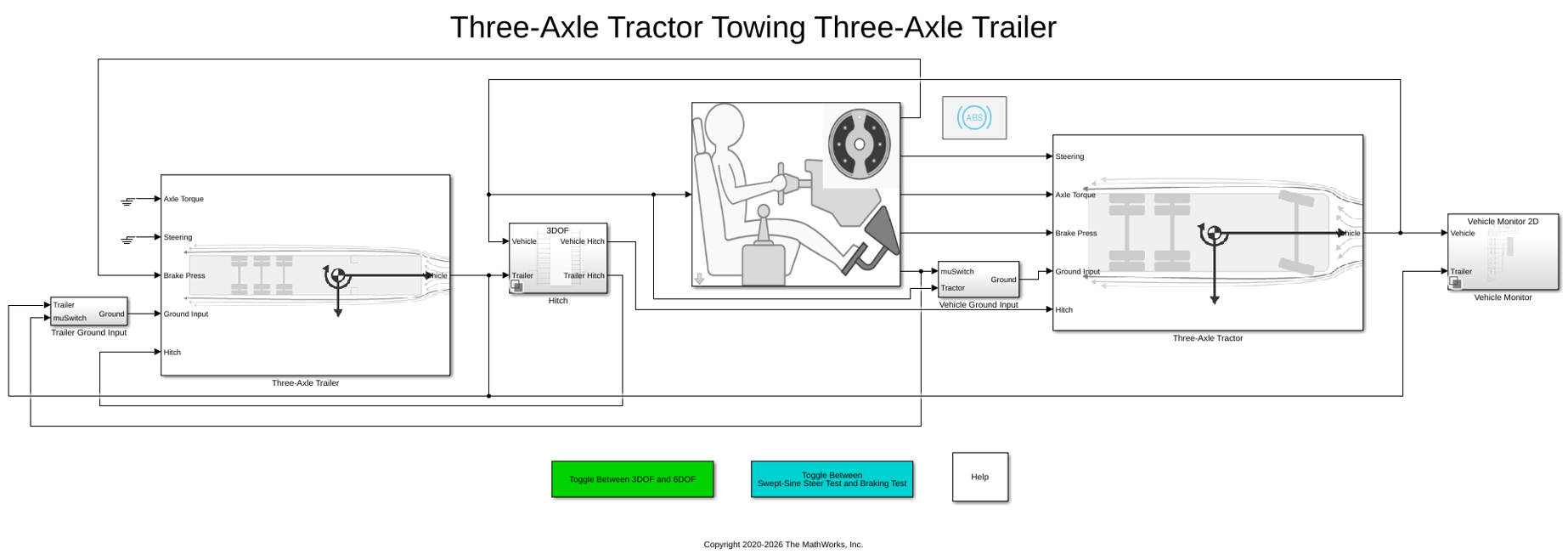
Three-Axle Tractor Towing a Three-Axle Trailer
Simulates three-axle tractor towing a three-axle trailer for commercial trucking applications. Implements hitch subsystem, sinusoidal wave steering or braking test, and axle torque applied to tractor rear wheels.
Ports
Input
Output
Parameters
References
[1] Gillespie, Thomas. Fundamentals of Vehicle Dynamics. Warrendale, PA: Society of Automotive Engineers (SAE), 1992.
Extended Capabilities
Version History
Introduced in R2020b

