Coordinate Systems in Vehicle Dynamics Blockset
Vehicle Dynamics Blockset™ uses these coordinate systems to calculate the vehicle dynamics and position objects in the 3D visualization environment.
Environment | Description | Coordinate Systems |
|---|---|---|
Vehicle dynamics in Simulink® | The right-hand rule establishes the X-Y-Z sequence and rotation of the coordinate axes used to calculate the vehicle dynamics. The Vehicle Dynamics Blockset 3D simulation environment uses these right-handed (RH) Cartesian coordinate systems defined in the SAE J670[2] and ISO 8855[3] standards:
The coordinate systems can have either orientation:
| |
3D visualization engine | To position objects and query the 3D visualization environment, the Vehicle Dynamics Blockset uses a world coordinate system. |
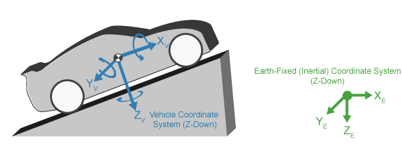
Earth-Fixed (Inertial) Coordinate System
The earth-fixed coordinate system (XE, YE, ZE) axes are fixed in an inertial reference frame. The inertial reference frame has zero linear and angular acceleration and zero angular velocity. In Newtonian physics, the earth is an inertial reference.
| Axis | Description |
|---|---|
| XE |
The XE axis is in the forward direction of the vehicle. The XE and YE axes are parallel to the ground plane. The ground plane is a horizontal plane normal to the gravitational vector. |
| YE | |
| ZE | Vertical, positive downward, parallel to gravitational vector. To transform from the Z-down orientation to the Z-up orientation apply a positive rotation of 180 degrees on the X-axis. |
Vehicle Coordinate System
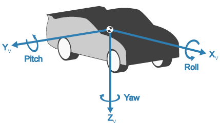
The vehicle coordinate system axes (XV, YV, ZV) are fixed in a reference frame attached to the vehicle. The origin is at the vehicle sprung mass.
Z-Down Orientation
| Axis | Description |
|---|---|
| XV | The XV axis points forward and is parallel to the vehicle plane of symmetry. |
| YV |
The YV axis is perpendicular to the vehicle plane of symmetry. In the Z-down orientation:
|
| ZV |
Tire and Wheel Coordinate Systems
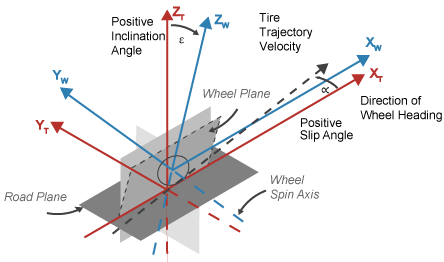
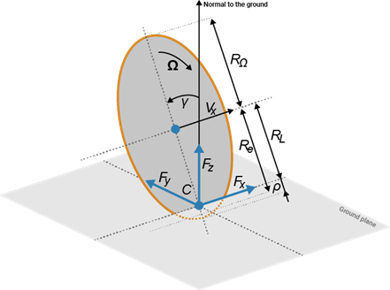
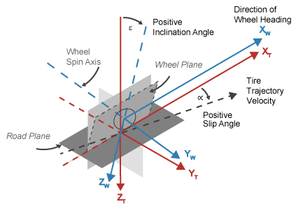
The tire coordinate system axes (XT, YT, ZT) are fixed in a reference frame attached to the tire. The origin is at the tire contact with the ground.
The wheel coordinate system axes (XW, YW, ZW) are fixed in a reference frame attached to the wheel. The origin is at the wheel center.
| Z-Up Orientationa | Z-Up Orientation with Radii and Deflection Defined | Z-Down Orientation |
|---|---|---|
|
|
|
|
a Reprinted with permission Copyright © 2008 SAE International. Further distribution of this material is not permitted without prior permission from SAE. | ||
| Axis | Description |
|---|---|
| XT | XT and YT are parallel to the road plane. The intersection of the wheel plane and the road plane define the orientation of the XT axis. |
| YT | |
| ZT | ZT points:
|
| XW | XW and YW are parallel to the wheel plane:
|
| YW | |
| ZW | ZW points:
|
World Coordinate System
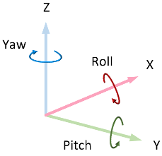
The 3D visualization environment uses a world coordinate system with axes that are fixed in the inertial reference frame.
| Axis | Description |
|---|---|
| X | Forward direction of the vehicle Roll — Right-handed rotation about X-axis |
| Y | Extends to the right of the vehicle, parallel to the ground plane Pitch — Right-handed rotation about Y-axis |
| Z | Extends upwards Yaw — Left-handed rotation about Z-axis |
References
[1] Gillespie, Thomas. Fundamentals of Vehicle Dynamics. Warrendale, PA: Society of Automotive Engineers, 1992.
[2] Vehicle Dynamics Standards Committee. Vehicle Dynamics Terminology. SAE J670. Warrendale, PA: Society of Automotive Engineers, 2008.
[3] Technical Committee. Road vehicles — Vehicle dynamics and road-holding ability — Vocabulary. ISO 8855:2011. Geneva, Switzerland: International Organization for Standardization, 2011.
See Also
Topics
- Coordinate Systems in Automated Driving Toolbox (Automated Driving Toolbox)
