Run Virtual Vehicle Model Through Standard Drive Cycle
To build your virtual vehicle, use the Virtual Vehicle
Composer app. After you build your virtual vehicle model, you can change the model
configuration to simulate standard vehicle drive cycles and the visualization environment.
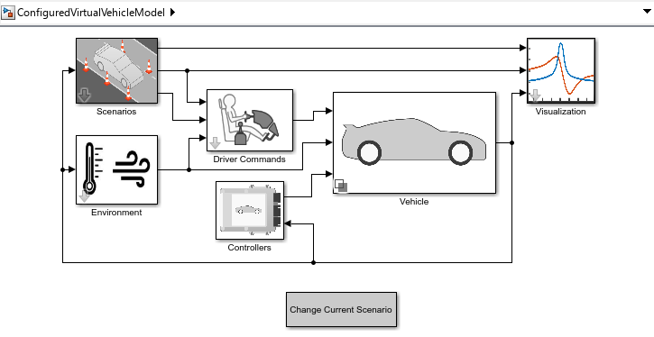
This example shows you how to run a virtual vehicle model,
ConfiguredVirtualVehicleModel, through the
FTP75 drive cycle.

To configure your virtual vehicle model to simulate a standard drive cycle, follow these steps.
| Workflow Step | Description |
|---|---|
After you build your virtual vehicle model, change the model
configuration to simulate standard drive cycles like the
| |
In the | |
On the |
Step 1: Configure Virtual Vehicle Model
After you build your virtual vehicle model, change the model configuration to simulate
standard testing drive cycles. In this example, update the Scenarios
and Driver Commands subsystems to configure the model to run the
standard drive cycle FTP75.
Scenarios
In the configured vehicle model, in Scenarios, select the
Drive Cycle variant.
In
ConfiguredVirtualVehicleModel, right-clickScenariosand select Mask > Look Under Mask.Right-click Reference Generator and select Variant > Label Model Active Choice. Select the maneuver. For this example, select Drive Cycle.

In the
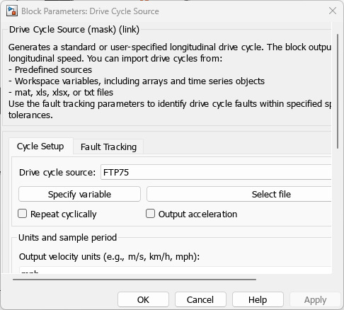
Scenariossubsystem, navigate toReference Generator>Drive Cycleand open the Drive Cycle Source block. Set Drive cycle source toFTP75.
Note
To install additional drive cycles from a support package, see Support Package for Maneuver and Drive Cycle Data. The support package has drive cycles that include gear shift schedules, for example
JC08andCUEDC.Save
ConfiguredVirtualVehicleModel.
Driver Commands
In the configured vehicle model, in Driver Commands, select the
Longitudinal Driver variant.
In
ConfiguredVirtualVehicleModel, right-clickDriver Commandsand select Mask > Look Under Mask.Right-click Driver Commands and select Variant > Label Model Active Choice. Select the driver. For this example, select Longitudinal Driver. The model implements the Longitudinal Driver block.

Save
ConfiguredVirtualVehicleModel.
Step 2: Configure Visualization
In the Visualization subsystem, you can select signals and options
to view simulation results. For this example, enable signal logging for the velocity signal.
In
ConfiguredVirtualVehicleModel, right-clickVisualizationand select Mask > Look Under Mask.Right-click the
Trace Velocity, Target, Action (mph)signal and select and enable signal logging.
Save
ConfiguredVirtualVehicleModel.
Step 3: Run Simulation
On the
ConfiguredVirtualVehicleModelmodel toolstrip, confirm the simulation stop time. For this drive cycle example, set Stop Time to2600.On the
ConfiguredVirtualVehicleModelmodel toolstrip, click Run. As the simulation runs, view the simulation results. For this example, view theTrace Velocitysignal for theFTP75drive cycle simulation.
See Also
Virtual Vehicle Composer | Longitudinal Driver | Drive Cycle Source