Refine View Graph Using Geometric Verification
In Structure-from-Motion (SfM) pipelines, appearance-based feature matching often proposes many candidate image pairs and putative correspondences. However, these matches can include a significant number of outliers due to repeated textures, illumination changes, or viewpoint differences. This example shows how to perform geometric verification [1] to filter these outlier pairs by enforcing projective geometry constraints.
Load Data
This example builds on the view graph created in the Create View Graph Using Bag of Features example. Ensure that the images used in the view graph are available on the path.
% Check if the image datastore exists. If not, load images.
if ~exist("imds", "var")
    downloadFolder = tempdir;
    imageFolder = fullfile(downloadFolder, "sfmTrainingDataTUMRGBD", "images");
    imds = imageDatastore(imageFolder);
end
Load the view graph created from the Create View Graph Using Bag of Features example.
% Check if a view graph exists in workspace. If not, load it from MAT file.
if ~exist("viewGraph", "var")
    viewGraphFile = fullfile(downloadFolder, "sfmTrainingDataTUMRGBD", "initialViewGraph.mat");
viewGraphData = load(viewGraphFile);
    viewGraph = viewGraphData.viewGraph;
end

% Create a copy of the initial graph for later comparison
viewGraphInitial = viewGraph;
Load camera intrinsic parameters, which will be used later in estimation of the essential matrix. This example assumes the camera has been calibrated. To calibrate a camera, use the Camera Calibrator app.
% Load camera intrinsics
intrinsicsFile = fullfile(downloadFolder, "sfmTrainingDataTUMRGBD", "cameraInfo.mat");
data = load(intrinsicsFile);
intrinsics = data.intrinsics;
Geometric Verification of Feature Matches Between Image Pair
Geometric verification is performed on the initial appearance-based associations between image pairs using epipolar geometry constraints. From a set of matched feature point sets, estimate 2-D geometric transforms including homography and the essential matrix. Both the essential matrix and homography can be used to enforce geometric constraints on matched points. Choose the geometric transform which yields the most inlier matches. This ensures that the majority of outliers are removed from the matched features.
% Pick one of the image pairs and visualize the matched features viewIds1 = viewGraph.Connections.ViewId1; viewIds2 = viewGraph.Connections.ViewId2; numConnections = viewGraph.NumConnections; connId =1; viewId1 = viewIds1(connId); viewId2 = viewIds2(connId); view1 = findView(viewGraph, viewId1); view2 = findView(viewGraph, viewId2); points1 = view1.Points{:}; points2 = view2.Points{:}; % Get the matched SIFT points matchedPairs = viewGraph.Connections.Matches{connId}; matchedPoints1 = points1(matchedPairs(:,1)); matchedPoints2 = points2(matchedPairs(:,2));
This example uses RANSAC to perform geometric verification. Configure the geometric verification and RANSAC model estimation parameters. The reprojection error threshold must reflect the expected accuracy of feature matches and the resolution of the input images. Lower thresholds are more selective but may reject valid matches. Additionally, setting a higher confidence level increases the number of RANSAC trials needed to find a reliable model, which can improve robustness but also increase computation time. These parameters directly affect the quality of geometric verification, so they must be tuned based on the characteristics of your dataset.
% Geometry verification parameters
% maxReprojectionError - Maximum reprojection error in pixels (for homography)
%                        or pixels^2 (Sampson error proxy)
% minNumInliers        - Minimum inlier count to accept a verified connection
% minInlierRatio       - General acceptance threshold for either transform
% minInlierRatioH      - High ratio for homography dominance (planar/pure rotation cases)
maxReprojectionError = 4;
minNumInliers        = 30;
minInlierRatio       = 0.25;
minInlierRatioH      = 0.8;

% RANSAC parameters
confidence      = 99.9;
maxNumTrials    = 100;

% Suppress warnings related to RANSAC for cleaner output.
warning("off","vision:ransac:maxTrialsReached");
warning("off","images:geotrans:transformationMatrixBadlyConditioned");
Estimate both a planar homography and an essential matrix for each matched image pair. Then, select the model that produces the highest number of inliers based on the specified reprojection error threshold.
This example assumes all images were captured using the same camera, so they share identical intrinsic parameters. However, in general SfM pipelines, the two images may have different intrinsics, which should be accounted for when estimating the essential matrix using the estimateEssentialMatrix function.
Note that the estgeotform2d uses a pixel-distance threshold, while estimateEssentialMatrix uses a Sampson distance as a proxy for geometric error. To keep the thresholds roughly comparable, square the pixel threshold when computing the essential matrix.
% Estimate homography
[~, inliersIndexH, statusH] = estgeotform2d(matchedPoints1, matchedPoints2, "projective", ...
    MaxNumTrials=maxNumTrials, MaxDistance=maxReprojectionError);

% Estimate essential matrix
[~, inliersIndexE, statusE] = estimateEssentialMatrix(matchedPoints1, matchedPoints2, intrinsics, intrinsics, ...
    MaxNumTrials=maxNumTrials, Confidence=confidence, MaxDistance=maxReprojectionError^2);

% Pick the one with more inlier matches
if ~statusH && ~statusE % Both are computed successfully
    if nnz(inliersIndexH) > nnz(inliersIndexE)
        inliersIndex = inliersIndexH;
    else
        inliersIndex = inliersIndexE;
    end
elseif ~statusH % Only homography is computed successfully
    inliersIndex = inliersIndexH;
elseif ~statusE % Only fundamental matrix is computed successfully
    inliersIndex = inliersIndexE;
else
    disp("No geometric transform can be found");
    return;
end
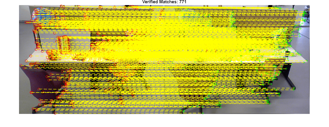
Visualize the initial putative matches and the geometrically verified inliers. This qualitative check helps confirm that outliers have been effectively removed while preserving correct correspondences.
% Read image pair
I1 = readimage(imds, viewId1);
I2 = readimage(imds, viewId2);

figure
showMatchedFeatures(I1, I2, matchedPoints1, matchedPoints2, "montage", PlotOptions={"ro","g+","y--"});
title("Initial Matches: " + matchedPoints1.Count);
truesize
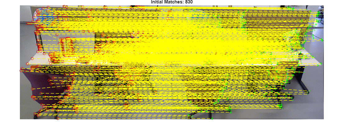
figure
showMatchedFeatures(I1, I2, matchedPoints1(inliersIndex), matchedPoints2(inliersIndex), "montage", PlotOptions={"ro","g+","y--"});
title("Verified Matches: " + nnz(inliersIndex));
truesize
Geometric Verification of Entire View Graph
After verifying individual image pairs, iterate over all edges in the view graph and remove connections that do not meet the geometric verification thresholds. Image pairs are considered verified if both the number and ratio of inlier feature matches exceed the specified thresholds. This step prunes weak or inconsistent edges from the view graph. As a result, the graph becomes more structurally consistent and contains connections between image pairs with strong geometric support.
% Initialize the status of edges
isInvalidConnection = false(viewGraph.NumConnections,1);

% Initialize the verified feature matching
verifiedMatches = cell(viewGraph.NumConnections,1);

% Geometric verification for all view graph edges
for connId = 1:viewGraph.NumConnections

    matchedPairs = viewGraph.Connections.Matches{connId};

    % View indexes for the two views being considered
    viewId1 = viewIds1(connId);
    viewId2 = viewIds2(connId);

    view1   = findView(viewGraph, viewId1);
    view2   = findView(viewGraph, viewId2);
    points1 = view1.Points{:};
    points2 = view2.Points{:};

    % Get the matched SIFT points
    matchedPoints1 = points1(matchedPairs(:,1));
    matchedPoints2 = points2(matchedPairs(:,2));

    % Estimate homograph
    [~, inliersIndexH, statusH] = estgeotform2d(matchedPoints1, matchedPoints2, "projective", ...
        MaxNumTrials=maxNumTrials, MaxDistance=maxReprojectionError);

    % Estimate essential matrix
    [~, inliersIndexE, statusE] = estimateEssentialMatrix(matchedPoints1, matchedPoints2, intrinsics, intrinsics, ...
        MaxNumTrials=maxNumTrials, Confidence=confidence, MaxDistance=maxReprojectionError^2);

    % Pick the one with more inlier matches
    if ~statusH && ~statusE % Both are computed successfully
        if nnz(inliersIndexH) > nnz(inliersIndexE)
            inliersIndex = inliersIndexH;
        else
            inliersIndex = inliersIndexE;
        end
    elseif ~statusH % Only homography is computed successfully
        inliersIndex = inliersIndexH;
    elseif ~statusE % Only fundamental matrix is computed successfully
        inliersIndex = inliersIndexE;
    else
        inliersIndex = [];
    end

    % Check inlier number and ratio
    numInliers    = nnz(inliersIndex);
    inlierRatio   = numInliers / matchedPoints1.Count;
    isVerified    = numInliers > minNumInliers && inlierRatio > minInlierRatio;

    if ~isVerified
        % Remove edge if geometric verification fails
        isInvalidConnection(connId) = true;
    else
        % Store the inlier matching of the edge
        verifiedMatches{connId} = matchedPairs(inliersIndex,:);
    end
end
Update the edges with verified feature matching. This ensures downstream 3-D reconstruction steps operate only on inlier correspondences.
for connId = 1:viewGraph.NumConnections
    if ~isInvalidConnection(connId)
        viewGraph = updateConnection(viewGraph, viewIds1(connId), viewIds2(connId), rigidtform3d(),...
            Matches=verifiedMatches{connId});
    end
end
Delete edges in the view graph that violate geometric constraints.
deleteConnList = viewGraph.Connections(isInvalidConnection, 1:2);
for i = 1:height(deleteConnList)
    viewId1 = deleteConnList.ViewId1(i);
    viewId2 = deleteConnList.ViewId2(i);
    if hasConnection(viewGraph,viewId1, viewId2)
        viewGraph = deleteConnection(viewGraph, viewId1, viewId2);
    end
end
disp(height(deleteConnList) + " of " + viewGraph.NumConnections + " edges were pruned from the view graph.")
331 of 423 edges were pruned from the view graph.
% Restore warnings after the loop
warning("on","vision:ransac:maxTrialsReached");
warning("on","images:geotrans:transformationMatrixBadlyConditioned");
Visualize Initial and Refined View Graphs
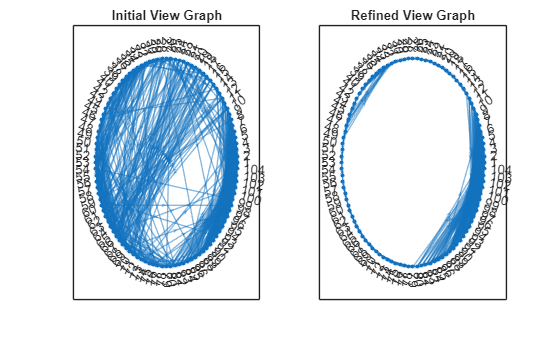
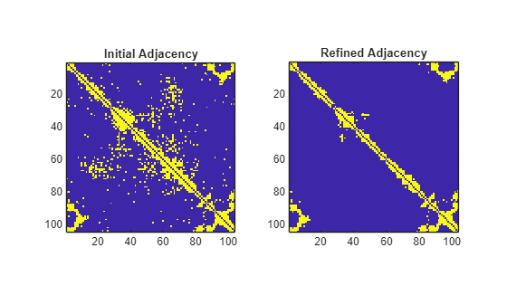
Plot the nodes and edges in the view graph and visualize the corresponding adjacency matrix. Because the images are captured sequentially, each node primarily connects to its immediate neighbors. After geometric verification, most long-range edges are removed since those image pairs lack sufficient scene overlap.
numImages = numel(imds.Files);

G1 = createPoseGraph(viewGraphInitial);
G2 = createPoseGraph(viewGraph);

figure
subplot(1,2,1)
plot(G1, NodeLabel=1:numImages, Layout="circle");
view(2)
title("Initial View Graph")

subplot(1,2,2)
plot(G2, NodeLabel=1:numImages, Layout="circle");
view(2)
title("Refined View Graph")
A1 = adjacency(G1);
A1 = A1+A1';
A2 = adjacency(G2);
A2 = A2+A2';

figure
subplot(1,2,1)
imagesc(A1)
axis image
title("Initial Adjacency")

subplot(1,2,2)
imagesc(A2)
axis image
title("Refined Adjacency")
Visualize Similar Images
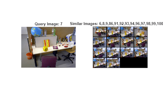
Visualize similar images after geometric verification. Because some edges are pruned from the view graph, the image may have fewer similar images than before.
queryIdx =7; viewTable = connectedViews(viewGraph, queryIdx); similarIdx = viewTable.ViewId; queryImg = readimage(imds, queryIdx); % Select and read similar images imdsSub = subset(imds, double(similarIdx)); retrievedImages = readall(imdsSub); figure subplot(1,2,1) imshow(queryImg) title("Query Image: " + queryIdx) subplot(1,2,2) montage(retrievedImages, BorderSize=5) title("Similar Images: " + strjoin(string(similarIdx), ","));
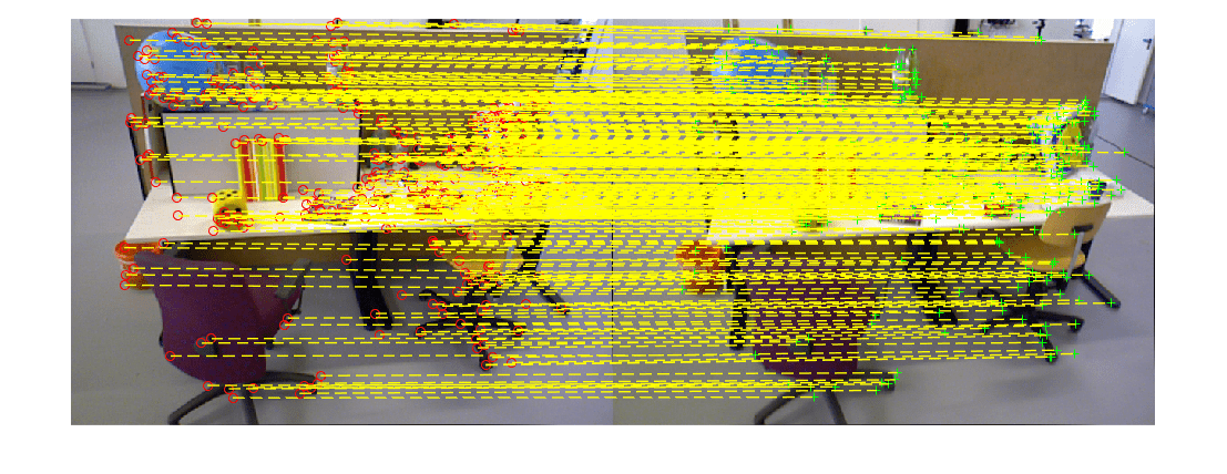
Visualize Matched Features
Visualize matched features for a selected connection. Note that the geometric verification has removed outliers from the initial feature matches.
% Pick one of the image pairs and visualize the matched features numConnections = viewGraph.NumConnections; connId =28; viewIds1 = viewGraph.Connections.ViewId1; viewIds2 = viewGraph.Connections.ViewId2; matchedPairs = viewGraph.Connections.Matches{connId}; viewId1 = viewIds1(connId); viewId2 = viewIds2(connId); view1 = findView(viewGraph, viewId1); view2 = findView(viewGraph, viewId2); points1 = view1.Points{:}; points2 = view2.Points{:}; % Get the matched SIFT points matchedPoints1 = points1(matchedPairs(:,1)); matchedPoints2 = points2(matchedPairs(:,2)); % Read image pair I1 = readimage(imds, viewId1); I2 = readimage(imds, viewId2); figure showMatchedFeatures(I1, I2, matchedPoints1, matchedPoints2, "montage", PlotOptions={"ro","g+","y--"}); truesize
With a structurally consistent and geometrically verified view graph, the next step is incremental structure-from-motion. The Reconstruct 3-D Scene from Geometrically Refined Pair of Initial Views example shows how to estimate relative pose between the image pair using the verified feature correspondences and then triangulate an initial set of 3-D points, which can help expand the reconstruction to additional views.
References
[1] Schonberger, Johannes L., and Jan-Michael Frahm. "Structure-from-motion revisited." In Proceedings of the IEEE conference on computer vision and pattern recognition, pp. 4104-4113. 2016.
See Also
imageviewset | estimateEssentialMatrix | estgeotform2d | findView