Border Effects
Classically, the DWT is defined for sequences with length of some power of 2, and different ways of extending samples of other sizes are needed. Methods for extending the signal include zero-padding, smooth padding, periodic extension, and boundary value replication (symmetrization).
The basic algorithm for the DWT is not limited to dyadic length and is based on a simple scheme: convolution and downsampling. As usual, when a convolution is performed on finite-length signals, border distortions arise.
Signal Extensions: Zero-Padding, Symmetrization, and Smooth Padding
To deal with border distortions, the border should be treated differently from the other parts of the signal.
Various methods are available to deal with this problem, referred to as “wavelets on the interval” [1]. These interesting constructions are effective in theory but are not entirely satisfactory from a practical viewpoint.
Often it is preferable to use simple schemes based on signal extension on the boundaries. This involves the computation of a few extra coefficients at each stage of the decomposition process to get a perfect reconstruction. It should be noted that extension is needed at each stage of the decomposition process.
Details on the rationale of these schemes are in Chapter 8 of the book Wavelets and Filter Banks, by Strang and Nguyen [2].
The available signal extension modes are as follows (see dwtmode):
Zero-padding (
'zpd'): This method is used in the version of the DWT given in the previous sections and assumes that the signal is zero outside the original support.The disadvantage of zero-padding is that discontinuities are artificially created at the border.
Symmetrization (
'sym'): This method assumes that signals or images can be recovered outside their original support by symmetric boundary value replication.It is the default mode of the wavelet transform in the toolbox.
Symmetrization has the disadvantage of artificially creating discontinuities of the first derivative at the border, but this method works well in general for images.
Smooth padding of order 1 (
'spd'or'sp1'): This method assumes that signals or images can be recovered outside their original support by a simple first-order derivative extrapolation: padding using a linear extension fit to the first two and last two values.Smooth padding works well in general for smooth signals.
Smooth padding of order 0 (
'sp0'): This method assumes that signals or images can be recovered outside their original support by a simple constant extrapolation. For a signal extension this is the repetition of the first value on the left and last value on the right.Periodic-padding (1) (
'ppd'): This method assumes that signals or images can be recovered outside their original support by periodic extension.The disadvantage of periodic padding is that discontinuities are artificially created at the border.
The DWT associated with these five modes is slightly redundant. But IDWT ensures a perfect reconstruction for any of the five previous modes whatever the extension mode used for DWT.
Periodic-padding (2) (
'per'): If the signal length is odd, the signal is first extended by adding an extra-sample equal to the last value on the right. Then a minimal periodic extension is performed on each side. The same kind of rule exists for images. This extension mode is used for SWT (1-D & 2-D).
This last mode produces the smallest length wavelet decomposition. But the extension mode used for IDWT must be the same to ensure a perfect reconstruction.
Before looking at an illustrative example, let us compare some properties of the theoretical Discrete Wavelet Transform versus the actual DWT.
The theoretical DWT is applied to signals that are defined on an infinite length time interval (Z). For an orthogonal wavelet, this transform has the following desirable properties:
Norm preservation
Let cA and cD be the approximation and detail of the DWT coefficients of an infinite length signal X. Then the l2–norm is preserved:
‖X‖2 = ‖cA‖2 + ‖cD‖2
Orthogonality
Let A and D be the reconstructed approximation and detail. Then, A and D are orthogonal and
‖X‖2 = ‖A‖2 + ‖D‖2
Perfect reconstruction
X = A + D
Since the DWT is applied to signals that are defined on a finite-length time interval, extension is needed for the decomposition, and truncation is necessary for reconstruction.
To ensure the crucial property 3 (perfect reconstruction) for arbitrary choices of
The signal length
The wavelet
The extension mode
the properties 1 and 2 can
be lost. These properties hold true for an extended signal of length usually larger
than the length of the original signal. So only the perfect reconstruction property
is always preserved. Nevertheless, if the DWT is performed using the periodic
extension mode ('per') and if the length of the signal is
divisible by 2J, where
J is the maximum level decomposition, the properties
1, 2, and
3 remain true.
Practical Considerations
The DWT iterative step consists of filtering followed by downsampling:
Apply lowpass filter then downsample by two to obtain approximation coefficients.
Apply highpass filter then downsample by two to obtain detail coefficients.
So conceptually, the number of approximation coefficients is one half the number of samples, and similarly for the detail coefficients.
In the real world, we deal with signals of finite length. With the desire of applying the theoretical DWT algorithm to the practical, the question of boundary conditions must be addressed: How should the signal be extended?
Before investigating the different scenarios, save the current boundary extension mode.
origmodestatus = dwtmode('status','nodisplay');
Periodic, Power of 2
Consider the following example. Load the noisdopp data. The signal has 1024 samples, which is a power of 2. Use dwtmode to set the extension mode to periodic. Then use wavedec to obtain the level-3 DWT of the signal using the orthogonal db4 wavelet.
load noisdopp
x = noisdopp;
lev = 3;
wav = 'db4';
dwtmode('per','nodisp')
[c,bk] = wavedec(x,lev,wav);
bk
bk = 1×5

         128         128         256         512        1024
The bookkeeping vector bk contains the number of coefficients by level. At each stage, the number of detail coefficients reduces exactly by a factor of 2. At the end, there are approximation coefficients.
Compare the -norms.
fprintf('l2-norm difference: %.5g\n',sum(x.^2)-sum(c.^2))l2-norm difference: 9.0658e-09
Obtain the reconstructed approximations and details by setting to 0 the appropriate segments of the coefficients vector c and taking the inverse DWT.
cx = c;
cx(bk(1)+1:end) = 0;
reconApp = waverec(cx,bk,wav);
cx = c;
cx(1:bk(1)) = 0;
reconDet = waverec(cx,bk,wav);
Check for orthogonality.
fprintf('Orthogonality difference: %.4g\n', ...
    sum(x.^2)-(sum(reconApp.^2)+sum(reconDet.^2)))
Orthogonality difference: 1.816e-08
Check for perfect reconstruction.
fprintf('Perfect reconstruction difference: %.5g\n', ...
    max(abs(x-(reconApp+reconDet))));
Perfect reconstruction difference: 1.6741e-11
The three theoretical DWT properties are preserved.
Periodic, Not Power of 2
Now obtain the three-level DWT of a signal with 1026 samples. Use the same wavelet and extension mode is above. The number of coefficients at stage n does not evenly divide the signal length.
x = [0 0 noisdopp];
[c,bk] = wavedec(x,lev,wav);
bk
bk = 1×5

         129         129         257         513        1026
Check for -norm preservation, orthogonality, and perfect reconstruction.
cx = c;
cx(bk(1)+1:end) = 0;
reconApp = waverec(cx,bk,wav);
cx = c;
cx(1:bk(1)) = 0;
reconDet = waverec(cx,bk,wav);

fprintf('l2-norm difference: %.5g\n',sum(x.^2)-sum(c.^2))
l2-norm difference: -1.4028
fprintf('Orthogonality difference: %.4g\n', ...
    sum(x.^2)-(sum(reconApp.^2)+sum(reconDet.^2)))
Orthogonality difference: -0.3319
fprintf('Perfect reconstruction difference: %.5g\n', ...
    max(abs(x-(reconApp+reconDet))));
Perfect reconstruction difference: 1.6859e-11
Perfect reconstruction is satisfied, but the -norm and orthogonality are not preserved.
Not Periodic, Power of 2
Obtain the three-level DWT of a signal with 1024. Use the same wavelet as above, but this time change the extension mode to smooth extension of order 1. The number of coefficients at stage n does not evenly divide the signal length.
dwtmode('sp1','nodisp')
[c,bk] = wavedec(x,lev,wav);
bk
bk = 1×5

         134         134         261         516        1026
Check for -norm preservation, orthogonality, and perfect reconstruction.
cx = c;
cx(bk(1)+1:end) = 0;
reconApp = waverec(cx,bk,wav);
cx = c;
cx(1:bk(1)) = 0;
reconDet = waverec(cx,bk,wav);

fprintf('l2-norm difference: %.5g\n',sum(x.^2)-sum(c.^2))
l2-norm difference: -113.58
fprintf('Orthogonality difference: %.4g\n', ...
    sum(x.^2)-(sum(reconApp.^2)+sum(reconDet.^2)))
Orthogonality difference: -2.678
fprintf('Perfect reconstruction difference: %.5g\n', ...
    max(abs(x-(reconApp+reconDet))));
Perfect reconstruction difference: 1.637e-11
Again, only perfect reconstruction is satisfied.
Restore the original extension mode.
dwtmode(origmodestatus,'nodisplay');To support perfect reconstruction for arbitrary choices of signal length, wavelet, and extension mode, we use frames of wavelets.
A frame is a set of functions that satisfy the following condition: there exist constants such that for any function , the frame inequality holds:
The functions in a frame are generally not linearly independent. This means that the function does not have a unique expansion in . Daubechies [3] shows that if is the dual frame and for some , and if not all equal , then .
If , the frame is called a tight frame. If and for all , the frame is an orthonormal basis. If , then energy is not necessarily preserved, and the total number of coefficients might exceed the length of the signal. If the extension mode is periodic, the wavelet is orthogonal, and the signal length is divisible by , where is the maximum level of the wavelet decomposition, all three theoretical DWT properties are satisfied.
Arbitrary Extensions
It is interesting to notice that if an arbitrary extension is used, and decomposition is performed using the convolution-downsampling scheme, perfect reconstruction is recovered using idwt or idwt2.
Create a signal and obtain the filters associated with the db9 wavelet.
x = sin(0.3*[1:451]);
w = 'db9';
[LoD,HiD,LoR,HiR] = wfilters(w);
Append and prepend length(LoD) random numbers to the signal. Plot the original and extended signals.
lx = length(x);
lf = length(LoD);
ex = [randn(1,lf) x randn(1,lf)];
ymin = min(ex);
ymax = max(ex);
subplot(2,1,1)
plot(lf+1:lf+lx,x)
axis([1 lx+2*lf ymin ymax]);
title('Original Signal')
subplot(2,1,2)
plot(ex)
title('Extended Signal')
axis([1 lx+2*lf ymin ymax])

Use the lowpass and highpass wavelet decomposition filters to obtain the one-level wavelet decomposition of the extended signal.
la = floor((lx+lf-1)/2);
ar = wkeep(dyaddown(conv(ex,LoD)),la);
dr = wkeep(dyaddown(conv(ex,HiD)),la);
Confirm perfect reconstruction of the signal.
xr = idwt(ar,dr,w,lx);
err0 = max(abs(x-xr))
err0 =
5.4701e-11
Image Extensions
Let us now consider an image example. Save the current extension mode. Load and display the geometry image.
origmodestatus = dwtmode('status','nodisplay');
load geometry
nbcol = size(map,1);
colormap(pink(nbcol))
image(wcodemat(X,nbcol))

Zero-Padding
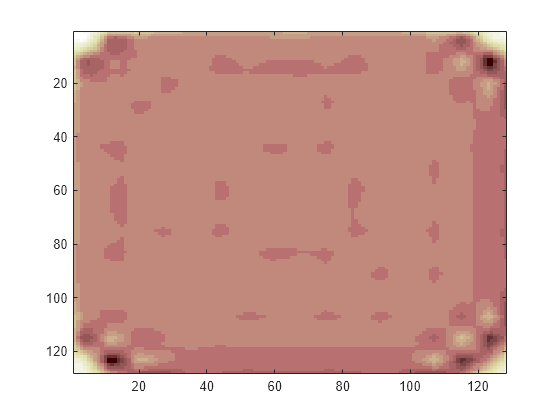
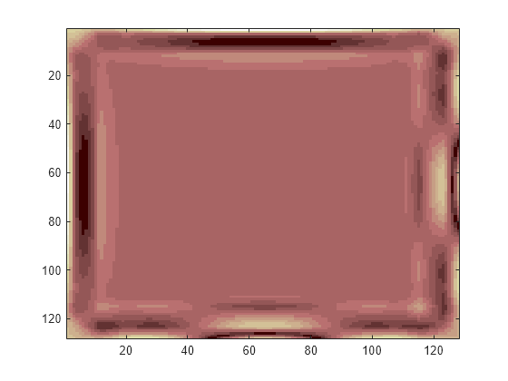
Set the extension mode to zero-padding and perform a decomposition of the image to level 3 using the sym4 wavelet. Then reconstruct the approximation of level 3.
lev = 3;
wname = 'sym4';
dwtmode('zpd','nodisp')
[c,s] = wavedec2(X,lev,wname);
a = wrcoef2('a',c,s,wname,lev);
image(wcodemat(a,nbcol))

Symmetric Extension
Set the extension mode to symmetric extension and perform a decomposition of the image to level 3 using the sym4 wavelet. Then reconstruct the approximation of level 3.
dwtmode('sym','nodisp')
[c,s] = wavedec2(X,lev,wname);
a = wrcoef2('a',c,s,wname,lev);
image(wcodemat(a,nbcol))

Smooth Padding
Set the extension mode to smooth padding and perform a decomposition of the image to level 3 using the sym4 wavelet. Then reconstruct the approximation of level 3.
dwtmode('spd','nodisp')
[c,s] = wavedec2(X,lev,wname);
a = wrcoef2('a',c,s,wname,lev);
image(wcodemat(a,nbcol))

Restore the original extension mode.
dwtmode(origmodestatus,'nodisplay')References
[1] Cohen, A., I. Daubechies, B. Jawerth, and P. Vial. "Multiresolution analysis, wavelets and fast algorithms on an interval." Comptes Rendus Acad. Sci. Paris Sér. A, Vol. 316, pp. 417–421, 1993.
[2] Strang, G., and T. Nguyen. Wavelets and Filter Banks. Wellesley, MA: Wellesley-Cambridge Press, 1996.
[3] Daubechies, I. Ten Lectures on Wavelets, CBMS-NSF Regional Conference Series in Applied Mathematics. Philadelphia, PA: SIAM Ed, 1992.