DVB-S2 HDL BCH Encoder
This example shows how to implement a DVB-S2 BCH encoder using Simulink® blocks that are optimized for HDL code generation.
To verify the behavior of the DVB-S2 HDL BCH Encoder example, you compare the output of the example with the bchEncode helper function.
Introduction
Digital Video Broadcast Satellite Second Generation (DVB-S2) is a European Telecommunications Standards Institute (ETSI) standard for digital data transmission through satellites. DVB-S2 offers powerful forward error correction (FEC) based on low-density parity-check (LDPC) codes concatenated with Bose-Chaudhuri-Hocquenghem (BCH) codes.
The FEC mechanism performs outer coding with BCH codes and inner coding with LDPC codes. This mechanism accepts baseband frames (BBFRAMEs) of  bits as input and gives out forward error correction frames (FECFRAMEs) of
  bits as output as specified in the section 5.3 of ETSI EN 302 307-1 [ 1 ]. This figure shows the frame format of FECFRAME data.
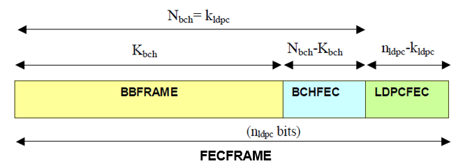
The DVB-S2 standard specifies 11 code rates for normal frames and 10 code rates for short frames. In tables 5a and 5b in the section 5.3 of [ 1 ], the standard defines BCH code rates for different uncoded block lengths and for different frame types.
Model Architecture
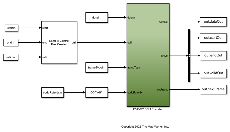
This figure shows the architecture block diagram of the DVB-S2 BCH Encoder example implementation.

This figure shows the top-level structure of the dvbs2hdlBCHEncoder model. You can generate the HDL code for the DVB-S2 BCH Encoder subsystem in the model.
modelName = 'dvbs2hdlBCHEncoder';
open_system(modelName);
set_param(modelName,'Open','on');
DVB-S2 BCH Encoder
The DVB-S2 BCH Encoder subsystem accepts input data, a control signal, a frame type, and a code rate index. The subsystem samples frameTypeIn and codeRateIdxIn signals at the start of the frame. The Input Controller subsystem controls the write and read operation of the input data to and from the RAM, respectively, inside the Store and Retrieve Input subsystem. The DVB-S2 BCH Encoder subsystem performs the BCH encoding after writing the whole frame to the RAM. Use tables 5a, 5b, 6a, and 6b in section 5.3 of [ 1 ] to calculate the generator polynomial. Using the Parity Generator subsystem, generate parity bits using the generator polynomial. This subsystem also stores and retrieves parity bits using RAM and performs parity indexing. Using the Output Controller subsystem, append the input data with the generated parity bits and generate output control signals.
set_param(modelName,'Open','off');
open_system([modelName '/DVB-S2 BCH Encoder']);
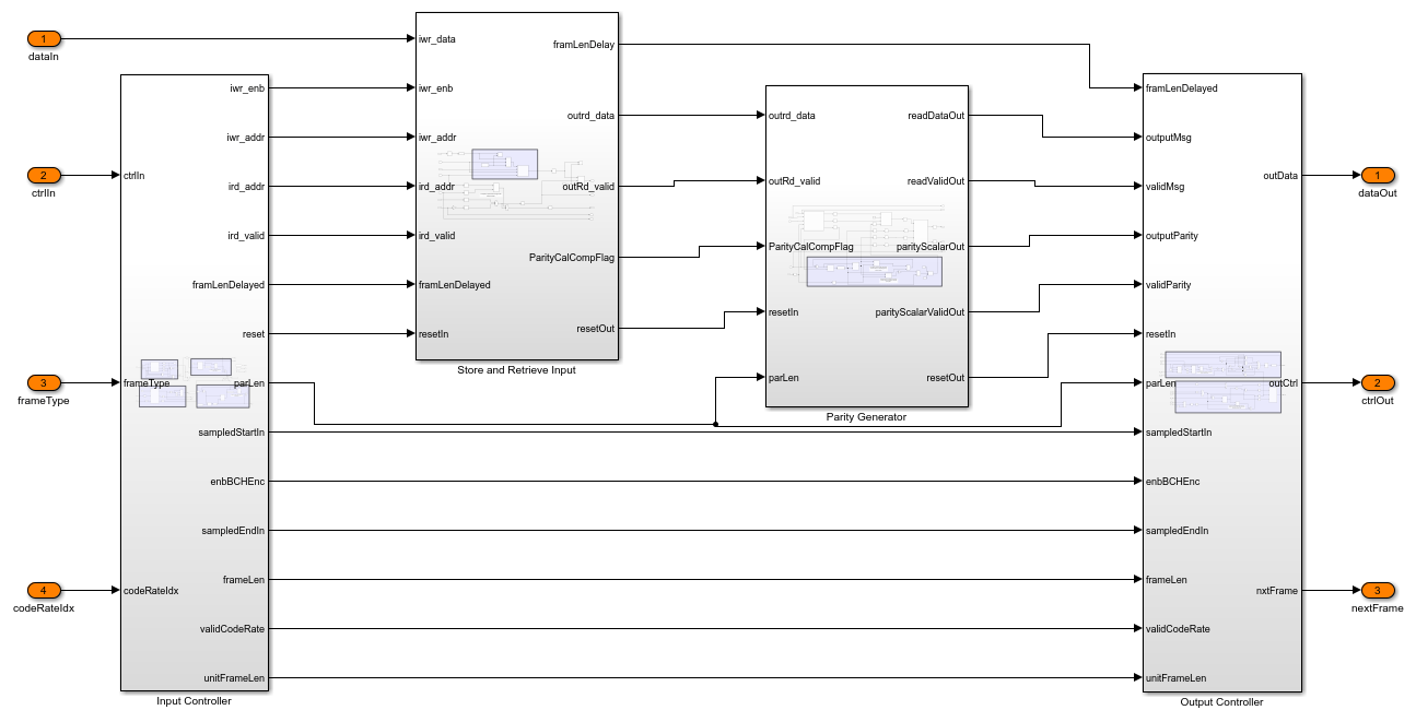
Input Controller
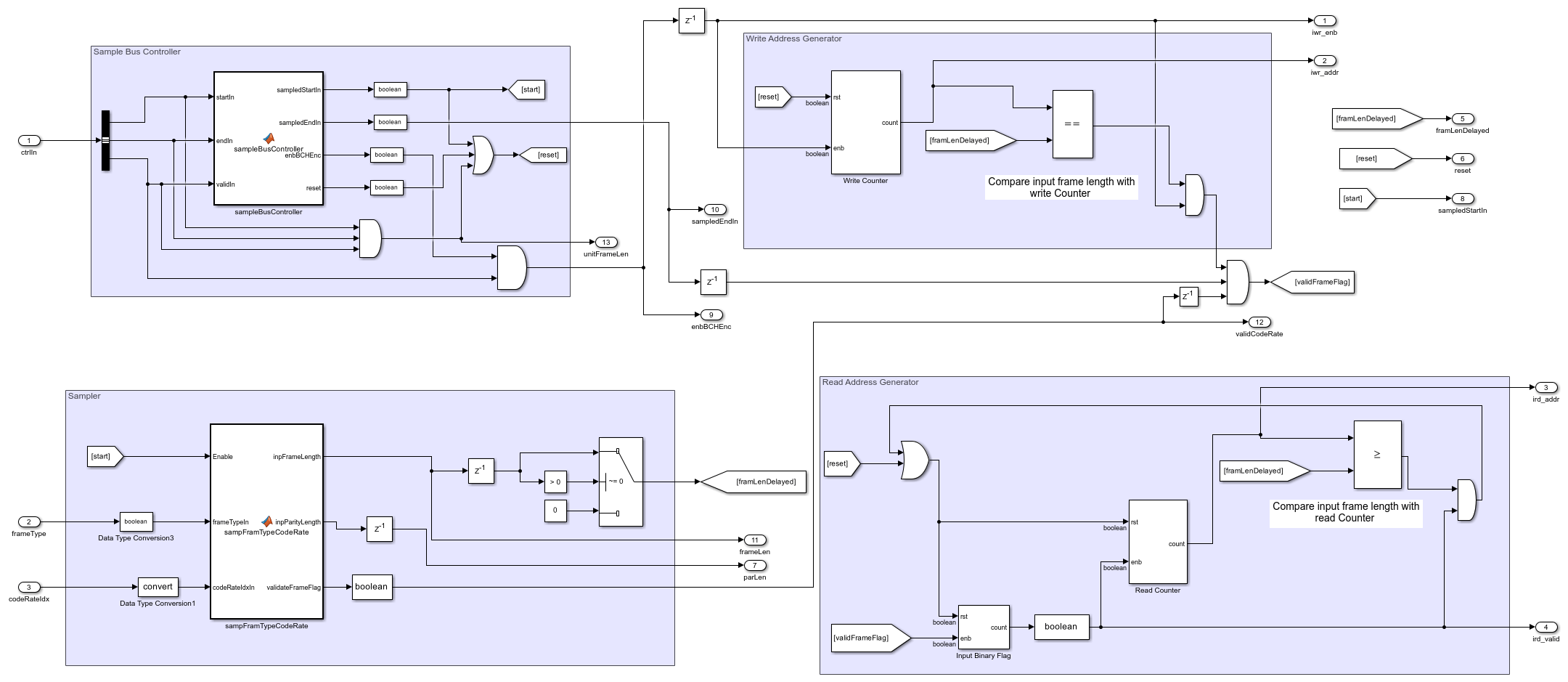
The Input Controller subsystem consists of these sections:
The Sample Bus Controller section accepts the input sample control bus and identifies the start, end, and valid signals. This section also generates the reset signal.
The Sampler section samples the frameType and codeRateIdx using start signal and outputs the corresponding input frame length and parity length. This section also validates frame parameters and returns the result in the validateFrameFlag indicator.
The Write Address Generator section has a write counter that runs till the input frame length and generates the address at which it stores the input bits inside the RAM.
The Read Address Generator section has a read counter that runs till the input frame length and generates the address for reading the stored input bits from the RAM. validFrameFlag signal enables read address generation only after storing the entire input frame inside the RAM.
set_param([modelName '/DVB-S2 BCH Encoder'],'Open','off');
open_system([modelName '/DVB-S2 BCH Encoder/Input Controller']);
Store and Retrieve Input
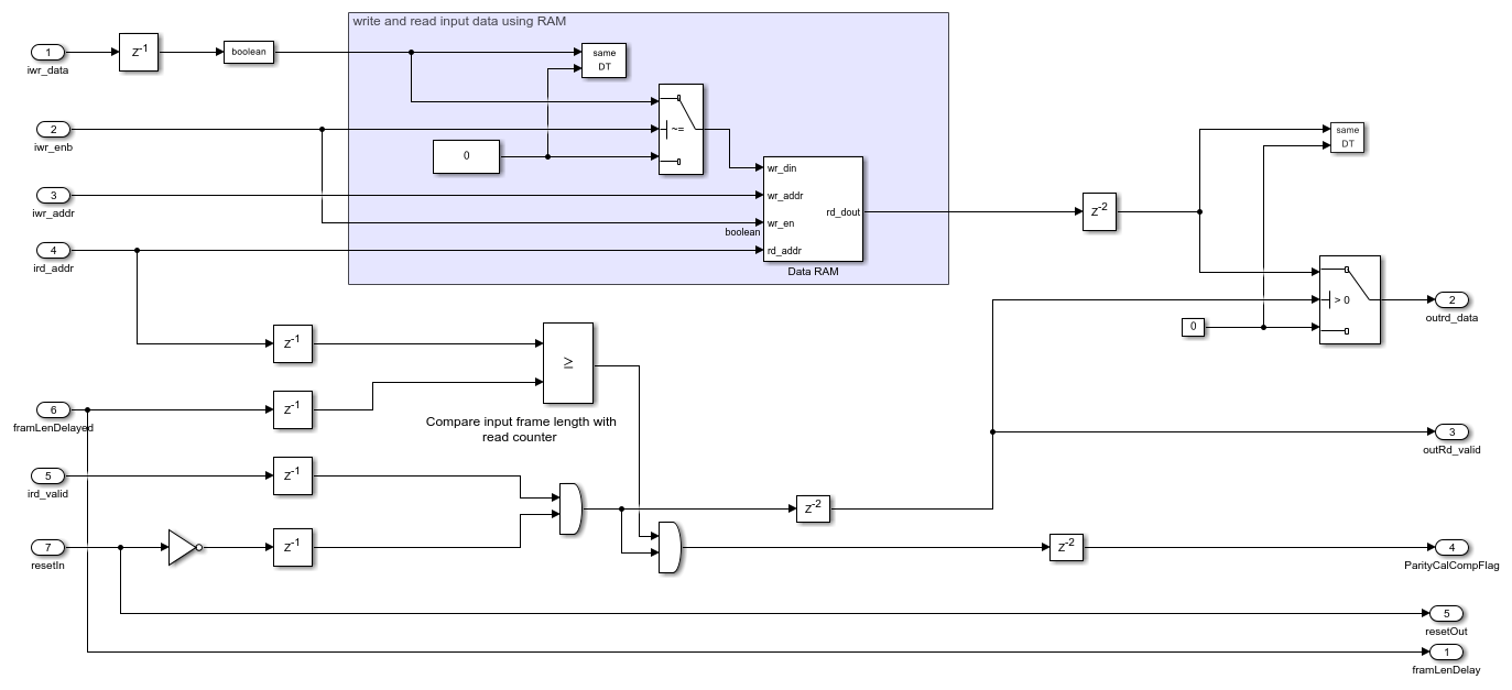
After generating the read and write address, the Store and Retrieve Input subsystem uses the Data RAM block to read and write the bits. For each high value of the outRd_valid signal, this subsystem reads a data bit from the Data RAM block and feeds it into the Parity Generator subsystem. The Store and Retrieve Input subsystem also compares the read addresses with the input frame length and indicates the end of the parity calculation using ParityCalCompFlag signal.
set_param([modelName '/DVB-S2 BCH Encoder'],'Open','off');
open_system([modelName '/DVB-S2 BCH Encoder/Store and Retrieve Input']);
Parity Generator
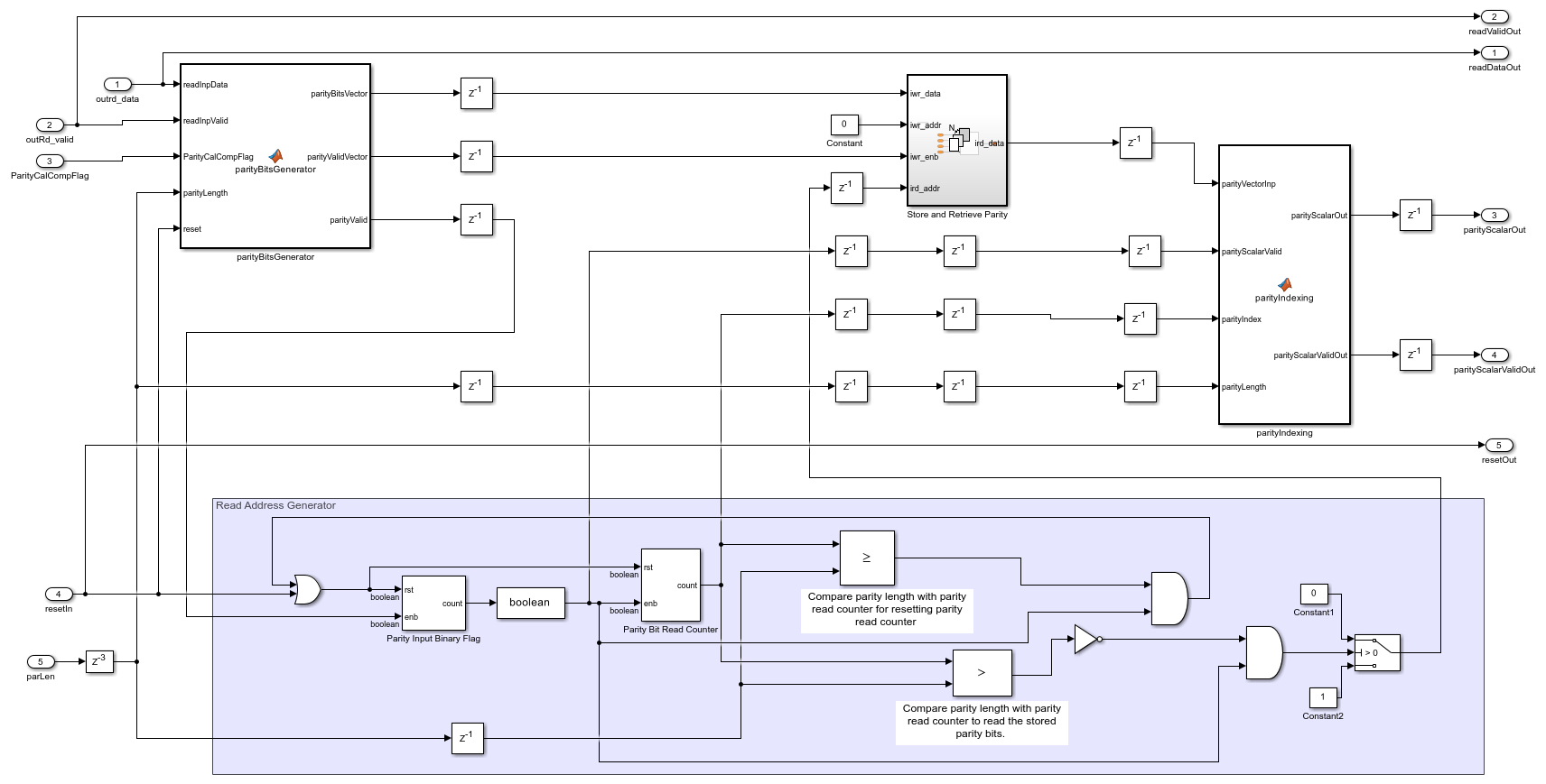
The parityBitsGenerator function generates a parity bit vector of length 192 for every input data bit according to the section 5.3.1 in [ 1 ]. For the parity lengths 168, 160, and 128, this function generates parity bit vectors of corresponding lengths appends zeros to create a vector of the length 192. The write address iwr_addr is always 0. The Read Address Generator section generates the read address. The Store and Retrieve Parity subsystem stores and retrieves the vector parity bits. The parityIndexing function block outputs the scalar parity bits from the parity vector based on the parity index that the Parity Bit Read Counter block generates.
set_param([modelName '/DVB-S2 BCH Encoder'],'Open','off');
open_system([modelName '/DVB-S2 BCH Encoder/Parity Generator']);
Output Controller
The Output Controller subsystem consists of these sections:
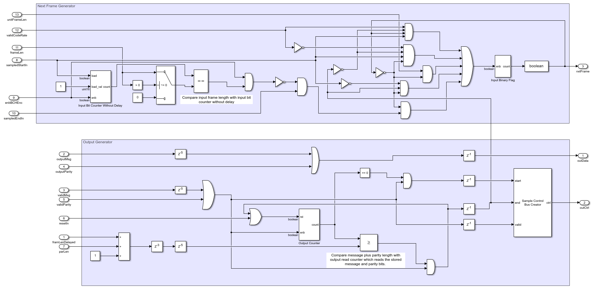
The Next Frame Generator generates the next frame logic using the previous state of nxtFrame, sampledStartIn, sampledEndIn, endOut, enbBCHEnc, unitFrameLen, validCodeRate, and frameLen signals.
The Output Generator section multiplexes the message and parity to generate the output data. This subsystem also generates the output sample control bus using an Output Counter block that runs till the output frame length.
set_param([modelName '/DVB-S2 BCH Encoder'],'Open','off');
open_system([modelName '/DVB-S2 BCH Encoder/Output Controller']);
Set Up Input Variables
Choose input values for the FEC frame type and the corresponding code rates according to the DVB-S2 standard. You can change the variable values in this section based on your requirements. Specify the codeRateIdx values as integers in the range [0, 10] that correspond to the codeRateSet values '1/4', '1/3', '2/5', '1/2', '3/5', '2/3', '3/4', '4/5', '5/6', '8/9', and '9/10'.
fecFrameSet = {'Normal','Short'};
codeRateSet = {'1/4','1/3','2/5','1/2','3/5','2/3','3/4','4/5','5/6','8/9','9/10'};

frameType = [1 0];   % FEC frame type
codeRateIdx = [1 0]; % Code rate index
numFrames = 2;
Generate Input Data
Generate inputs for the bchEncode helper function with the specified frame type and code rate variables. Create vectors of the frame type and code rate index using the frameTypeIn and codeRateIdxIn variables, respectively. Convert the frames of input data to samples with a control bus signal that indicates the frame boundaries. Provide these vectors and the control bus as inputs to the DVB-S2 BCH Encoder subsystem.
The encFrameGap variable accommodates the latency of the DVB-S2 BCH Encoder subsystem for the specified block length and code rate.
fecFrameType = fecFrameSet(frameType+1);
codeRate = codeRateSet(codeRateIdx+1);
msg = {numFrames};
refOut = cell(1,numFrames);

encSampleIn = [];
encStartIn = [];
encEndIn = [];
encValidIn = [];
fFrameIn = [];
codeRateIn = [];

for framIdx = 1:numFrames
    fFrame =  fecFrameType{framIdx};

    % Input and code word length calculation
    if strcmpi(fFrame,'Normal')
        cwLen = 64800;
        inpFrameLenList = [16008 21408 25728 32208 38688 43040 48408 51648 53840 57472 58192];
        inpRateList = [1/4 1/3 2/5 1/2 3/5 2/3 3/4 4/5 5/6 8/9 9/10];
        frameLenArr = inpFrameLenList(inpRateList == str2num(codeRate{framIdx}));
        frameLen = frameLenArr(1);
    else
        cwLen = 16200;
        inpFrameLenList = [3072  5232  6312  7032  9552 10632 11712 12432 13152 14232];
        inpRateList = [1/4 1/3 2/5 1/2 3/5 2/3 3/4 4/5 5/6 8/9];
        frameLenArr = inpFrameLenList(inpRateList == str2num(codeRate{framIdx}));
        frameLen = frameLenArr(1);
    end
    inpLen = frameLen;

    % Input bits generation
    msg{framIdx} = (randi([0 1],inpLen,1));

    % BCH encoding
    refOut{framIdx} = satcom.internal.dvbs.bchEncode(int8(msg{framIdx}),inpLen,cwLen);

    % Select the value cwLen*2 to accommodate the maximum latency of the
    % block considering different frame type and code rate configurations
    encFrameGap = cwLen*2;

    encSampleIn = [encSampleIn msg{framIdx}' zeros(1,encFrameGap)]; %#ok<*AGROW>
    encStartIn = logical([encStartIn 1 zeros(1,inpLen-1) zeros(1,encFrameGap)]);
    encEndIn = logical([encEndIn zeros(1,inpLen-1) 1 zeros(1,encFrameGap)]);
    encValidIn = logical([encValidIn ones(1,inpLen) zeros(1,encFrameGap)]);
    fFrameIn = logical([fFrameIn repmat(frameType(framIdx),1,inpLen) zeros(1,encFrameGap)]);
    codeRateIn = [codeRateIn repmat(codeRateIdx(framIdx),1,inpLen) zeros(1,encFrameGap)];
end

dataIn = logical(encSampleIn');
startIn = encStartIn;
endIn = encEndIn;
validIn = encValidIn;
frameTypeIn = fFrameIn;
codeRateIdxIn = codeRateIn;

simTime = length(encValidIn);
Run Simulink Model
The DVB-S2 BCH Encoder subsystem contains the implementation of the DVB-S2 BCH Encoder. Run the model to import the input signal variables dataIn, startIn, endIn, validIn, frameTypeIn, codeRateIdxIn, and simTime to the example from the script. The model exports a stream of encoded output samples encOut and a control bus containing startOut, endOut, and validOut signals to the MATLAB® workspace.
enc = sim(modelName);
Compare Block Output with Function Output
Convert the streaming output data of the DVB-S2 BCH Encoder subsystem to frames. Compare the frames with the output of the bchEncode helper function.
startIdx = find(squeeze(enc.startOut));
endIdx = find(squeeze(enc.endOut));
encData = squeeze(enc.dataOut);

encHDL = {numFrames};
for framIdx = 1:numFrames
    idx = startIdx(framIdx):endIdx(framIdx);
    encHDL{framIdx} = encData(idx);
    HDLOutput = double(encHDL{framIdx}(1:length(refOut{framIdx})));
    error = sum(abs(double(refOut{framIdx})-HDLOutput(:)));
    fprintf('Encoded %s FEC frame and code rate %s: Output data differs by %d bits\n',fecFrameType{framIdx},codeRate{framIdx},error);
end
Encoded Short FEC frame and code rate 1/3: Output data differs by 0 bits
Encoded Normal FEC frame and code rate 1/4: Output data differs by 0 bits
Calculate Latency
The latency of the DVB-S2 BCH Encoder in this example is  clock cycles, where
  is input frame length of the BCH encoder.
This figure shows the latency of the DVB-S2 BCH Encoder example when you set the frameType input port to 0 and the codeRateIdx input port to 3.

Generate HDL Code
To check and generate HDL code for this example, you must have an HDL Coder™ license. Use the makehdl and makehdltb commands to generate the HDL code and test bench for the DVB-S2 BCH Encoder subsystem.
Synthesize the DVB-S2 BCH Encoder subsystem on a Xilinx® Xilinx Zynq® UltraScale+ RFSoC xczu29dr-ffvf1760-2-e. This table shows the resource utilization results.
F = table(...
    categorical({'Slice LUT';'Slice Registers';'RAMB36';'DSP'; ...
    'Max. Frequency (MHz)'}) ,...
    categorical({'1401';'1032';'2';'0';'602.71'}), ...
    'VariableNames',{'Resources','Values'});

disp(F);
         Resources          Values
    ____________________    ______

    Slice LUT               1401
    Slice Registers         1032
    RAMB36                  2
    DSP                     0
    Max. Frequency (MHz)    602.71
References
ETSI 302 307-1 "Second generation framing structure, channel coding and modulation systems for Broadcasting, Interactive Services, News Gathering and other broadband satellite applications; Part 1: DVB-S2." Digital Video Broadcasting. https://www.etsi.org