HDL Implementation of AWGN Generator
This example shows the implementation of an additive white Gaussian noise (AWGN) generator that is optimized for HDL code generation and hardware implementation. The hardware implementation of AWGN accelerates the performance evaluation of wireless communication systems using an AWGN channel. In this example, the Simulink® model accepts signal-to-noise ratio (SNR) values as inputs and generates Gaussian random noise along with valid signal. The example supports SNR input ranges from –20 to 31 dB in steps of 0.1 dB.
Modern wireless communication systems includes many different simulation parameters, such as channel bandwidth, modulation type, and code rate. The performance evaluation of these systems with these simulation parameters is a bottleneck. Hardware capabilities of FPGAs can speed up simulations.
Model Architecture
% Run this command to open the whdlAWGNGenerator model.
modelname = 'whdlAWGNGenerator';
open_system(modelname);

This example demonstrates the implementation of an AWGN generator based on the Box-Muller method. The Box-Muller method is widely adopted for Gaussian noise generation because of its hardware-friendly architecture and constant output rate. The top-level structure of the model includes these three subsystems.
SNR dB to Linear Scale Converter
Gaussian Noise Generator with Unit Variance
Gaussian Noise Generator with Required Variance
% Run this command to open the subsystems inside AWGNGenerator model.
open_system([modelname '/AWGNGenerator']);

SNR dB to Linear Scale Converter
The dBtoLinearConverter subsystem takes an SNR value in dB as input and converts it into noise variance in a linear scale. This noise power is used to multiply the output of the Gaussian noise with unit variance. This lookup table approach is used for converting an SNR value in dB to a noise power value in a linear scale. During the conversion, the signal power is assumed to be 1. This subsystem has a latency of 1 clock cycle.
Gaussian Noise Generator with Unit Variance
The GaussianNoiseWithUnitVar subsystem generates Gaussian noise with unit variance by using the Box-Muller method. The Box-Muller method uses two uniformly distributed random variables to generate two normally distributed random variables through a series of logarithmic, square root, sine, and cosine operations as shown in this figure. Those two uniformly distributed random varibles are generated using the Tausworthe algorithm.

Implementation of HDL Tausworthe Uniform Random Number
The Tausworthe Uniform Random Number Generator module is used to generate two 32-bit uniform random integers. Each 32-bit uniform random number with improved statistical properties is obtained by combining three linear feedback shift register (LFSR) based uniform random number generators (URNGs). This implementation requires these two seeds: TausURNG1 and TausURNG2. The whdlexamples.hdlawgnGen_init.m script file initializes these seeds.
The ConcatandExtract subsystem accepts 32-bit uniform random integers, a and b, to generate two uniform random numbers, u0 and u1, in the range [0, 1) with bit-widths 48 and 16, respectively. u0 is generated by concatenating the 32-bit value of a and higher 16 bits of b. Uniform random number u1 is generated by extracting the lower 16 bits of b.
open_system([modelname '/AWGNGenerator/GaussianNoiseWithUnitVar/TausUniformRandGen']);
close_system([modelname '/AWGNGenerator/GaussianNoiseWithUnitVar/TausUniformRandGen']);
open_system([modelname '/AWGNGenerator/GaussianNoiseWithUnitVar/TausUniformRandGen/TausURNG1']);
close_system([modelname '/AWGNGenerator/GaussianNoiseWithUnitVar/TausUniformRandGen/TausURNG1']);
Warning: Unrecognized function or variable
'CloneDetectionUI.internal.CloneDetectionPerspective.register'.
Implementation of HDL Logarithm
HDL logarithm subsystem evaluates the approximate logarithm based on the piecewise linear polynomial method. This module has latency of 3 clock cycles. Implementation of the HDL logarithm involves these three steps.
Range Reduction – In this step, the original range of the input, which is [0, 1-2^(–48)) is reduced to a more convenient smaller range of [1, 2). The log function is approximated on the reduced range in the next step.
Function Evaluation – The log function is approximated over 256 equally spaced segments in the range [1, 2) by using a second-degree polynomial. Coefficients of the second-degree polynomial are obtained using the
polyfitfunction. These coefficients are stored in a lookup table, which is indexed using the first 8 bits of input to the function evaluation block.Range Reconstruction – The result of the function evaluation is expanded back to the original range. A bit left shift operation is used for range reconstruction and to implement the
–2*logfunction.
Run this command to open HDL logarithm subsystem.
open_system([modelname '/AWGNGenerator/GaussianNoiseWithUnitVar/logImplementation/log']);
Warning: Unrecognized function or variable
'CloneDetectionUI.internal.CloneDetectionPerspective.register'.

Implementation of HDL Square Root
The HDL Square root subsystem evaluates approximate square root based on the piecewise linear polynomial method. This module has a latency of 2. The implementation of the HDL square root involves these three steps.
Range Reduction – The input data type to the module is
fi(0, 31, 24). This range is reduced to a smaller range of [1, 4). The square root function is approximated on the reduced range in the next step.Function Evaluation – The square root function is approximated over 64 equally spaced segments in the range [1, 2) and [2, 4) by using a first-degree polynomial. Coefficients of the first-degree polynomial are stored in a lookup table, which is indexed using the first 6 bits of input to the function evaluation block.
Range Reconstruction – The result of the function evaluation is expanded back to the original range using a left shift operation.
close_system([modelname '/AWGNGenerator/GaussianNoiseWithUnitVar/logImplementation/log']);
open_system([modelname '/AWGNGenerator/GaussianNoiseWithUnitVar/SqrtImplementation/SqrtEval']);
Warning: Unrecognized function or variable
'CloneDetectionUI.internal.CloneDetectionPerspective.register'.

Implementation of HDL Sine and Cosine
The HDL optimized implementation of a sine or cosine function uses a lookup table approach. Sin and Cos are implemented using the existing Sine HDL Optimized and Cosine HDL Optimized (HDL Coder) blocks in the HDL Coder / Lookup Tables library.
close_system([modelname '/AWGNGenerator/GaussianNoiseWithUnitVar/SqrtImplementation/SqrtEval']);
Gaussian Noise Generator with Required Variance
The GaussianNoiseWithReqVar subsystem converts Gaussian noise with unit variance to Gaussian noise with required variance. This subsystem takes inputs from dBToLinearConvertor and GaussianNoiseWithUnitVar subsystems. The linear noise variance obtained from dBToLinearConvertor is multiplied with normally distributed random variables obtained from GaussianNoiseWithUnitVar.
Results and Plots
The whdlexamples.hdlawgnGen_init.m script file is used to specify the SNR range, generate the required number of noise samples, initialize the seeds for TausURNG1 and TausURNG2 subsystem and to generate coefficients for the function evaluation of the HDL log and square root.
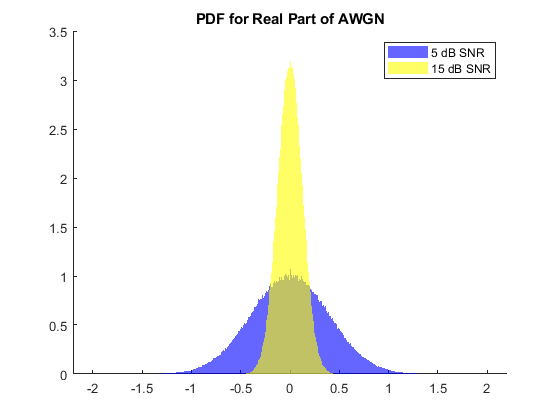
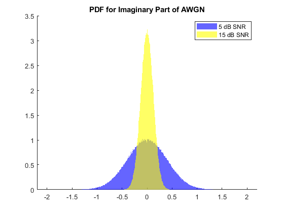
The whdlexamples.hdlawgnGen_init.m script file is the initialization function of whdlAWGNGenerator model. This function generates the input data and initializes the seeds for tausURNG and coefficients for the function evaluation. Simulate whdlAWGNGenerator.slx to generate 10^6 valid AWGN samples for each SNR of 5 dB and 15 dB. The implementation is pipelined to maximize the synthesis frequency, generating AWGN with an initial latency of 37. Plot the probability density function (PDF) of the AWGN output.
latency = 37;
NumOfSamples = 10^6;

% Simulate the model
open_system(modelname);
set_param(gcs,'SimulationMode','Accel');
fprintf('\n Simulating HDL AWGN Generator...\n');
outSimulink = sim(modelname,'ReturnWorkspaceOutputs','on');
fprintf('\n Simulation complete.\n');
awgnSimulink = outSimulink.awgnOut;

% Plot PDF
figure;
title('PDF for Real Part of AWGN');
hold on
histogram(real(awgnSimulink(latency+1:NumOfSamples+latency)),500, ...
        'Normalization','pdf','BinLimits',[-2 2],'FaceColor','blue', ...
        'EdgeColor','none');
histogram(real(awgnSimulink(NumOfSamples+latency+1:end)),500,...
        'Normalization','pdf','BinLimits',[-2 2],'FaceColor','yellow', ...
        'EdgeColor','none');
legend('5 dB SNR','15 dB SNR');

figure;
title('PDF for Imaginary Part of AWGN');
hold on
histogram(imag(awgnSimulink(latency+1:NumOfSamples+latency)),500, ...
        'Normalization','pdf','BinLimits',[-2 2],'FaceColor','blue', ...
        'EdgeColor','none');
histogram(imag(awgnSimulink(NumOfSamples+latency+1:end)),500, ...
        'Normalization','pdf','BinLimits',[-2 2],'FaceColor','yellow', ...
        'EdgeColor','none');
legend('5 dB SNR','15 dB SNR');
 Simulating HDL AWGN Generator...

 Simulation complete.

Verification
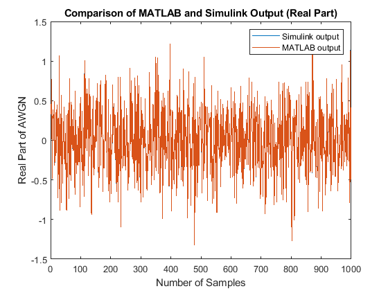
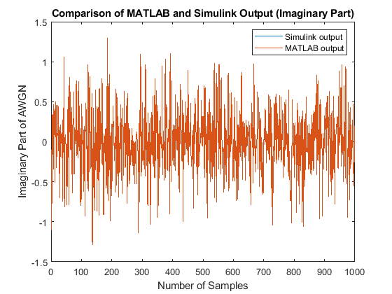
Compare the output of the AWGN Simulink model with the output of the HDL equivalent AWGN MATLAB® function.
NumOfSamples = 1000;
% MATLAB output
fprintf('\n Simulating MATLAB HDL AWGN Generator for comparison...\n');
awgnMatlab=whdlexamples.hdlawgn(snrdBSimInput(1:NumOfSamples),seedsURNG1,seedsURNG2);
fprintf('\n Simulation complete. \n')

% Compare MATLAB and Simulink outputs
figure;
ax=axes('FontSize', 20);
plot(1:1000,real([awgnSimulink(latency+1:NumOfSamples+latency) awgnMatlab]));
xlabel(ax,'Number of Samples');
ylabel(ax,'Real Part of AWGN');
title(ax,'Comparison of MATLAB and Simulink Output (Real Part)');
legend('Simulink output','MATLAB output');

figure;
ax=axes('FontSize', 20);
plot(1:1000,imag([awgnSimulink(latency+1:NumOfSamples+latency) awgnMatlab]));
xlabel(ax,'Number of Samples');
ylabel(ax,'Imaginary Part of AWGN');
title(ax,'Comparison of MATLAB and Simulink Output (Imaginary Part)');
legend('Simulink output','MATLAB output');
 Simulating MATLAB HDL AWGN Generator for comparison...

 Simulation complete.
HDL Code Generation
To check and generate the HDL code referenced in this example, you must have an HDL Coder™ license.
To generate the HDL code, enter this command at the MATLAB command prompt.
makehdl('whdlAWGNGenerator/AWGNGenerator')
To generate a test bench, enter this command at the MATLAB command prompt.
makehdltb('whdlAWGNGenerator/AWGNGenerator')
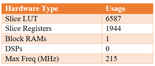
In this example, HDL code generated for the AWGNGenerator module is implemented for the AMD® Zynq®-7000 ZC706 board. The implementation results are shown in this table.
References
1. J.D. Lee, J.D. Villasenor, W. Luk, and P.H.W. Leong. “A Hardware Gaussian Noise Generator Using the Box-Muller Method and Its Error Analysis,” 659–71. IEEE, 2006. https://doi.org/10.1109/TC.2006.81.