Performance Evaluation of TDMA-Based MANET
This example shows how to model a time division multiple access (TDMA) based mobile ad hoc network (MANET) and measure the network performance.
Using this example, you can:
Configure and simulate a TDMA-based MANET.
Specify the TDMA frame structure for the network and assign one or more transmission slots to nodes.
Configure and install application traffic pattern at the nodes for unicast and broadcast transmissions.
Configure the physical layer (PHY) error modeling and channel modeling with impairments such as path loss.
Visualize the live network topology.
Analyze various application layer (APP), medium access control (MAC) layer, and PHY layer statistics available at the nodes, and evaluate performance metrics such as throughput, packet delivery ratio (PDR), and average end-to-end delay of the network.
Additionally, you can simulate a multihop network using the ad hoc on-demand distance vector (AODV) routing protocol. For more information, see AODV Routing in TDMA-Based MANET.
TDMA-Based MANET
A MANET consists of wireless nodes that communicate without fixed infrastructure. The nodes dynamically organize themselves and continuously adapt their topology. Each node can function as a source, destination, or relay for network packets.
MANETs use a TDMA-based MAC to grant channel access to the nodes. TDMA divides time into repeating frames, each containing a fixed number of slots. The slot assignment mechanism allocates distinct slots to nodes so only one node transmits per slot, preventing collisions. The mechanism assigns slots in two ways:
Static Assignment — You can assign specific slots to nodes when forming the network. Nodes use these slots for all transmissions. Static assignment suits networks with predictable traffic. When a node remains silent, its slot stays unused, resulting in lower bandwidth efficiency.
Dynamic Assignment — Nodes dynamically request slots when they need to send data, and they release them afterward.
This example uses static slot assignment.
Simulation Scenario
This example simulates a single-hop TDMA network with eight nodes.
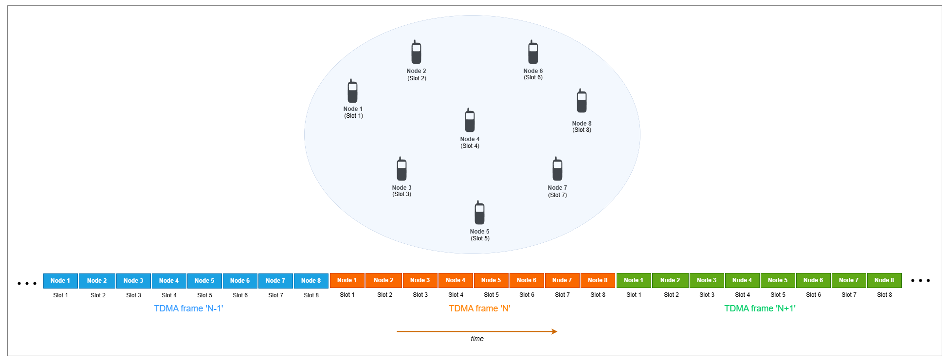
Each node in the network acts as a source and a destination, and receives a single slot within the TDMA frame.
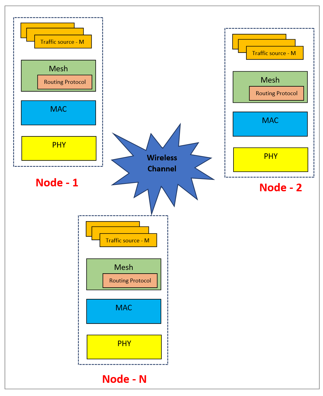
TDMA Node Stack
The hTDMANode helper object implements a TDMA node. The protocol stack of the node consists of three layers: mesh, MAC, and PHY. The application traffic models feed data into this stack. The TDMA nodes exchange packets over a wireless medium. The radio channel applies free space path loss (FSPL), which reduces the signal strength over distance.
This figure shows the protocol stack of TDMA nodes.
Traffic Source
You can install one or more applications on a node. These applications send traffic to other nodes in the network. You can assign a priority level to each application. During its transmission slots, a node always sends higher priority traffic before lower priority traffic.
Mesh
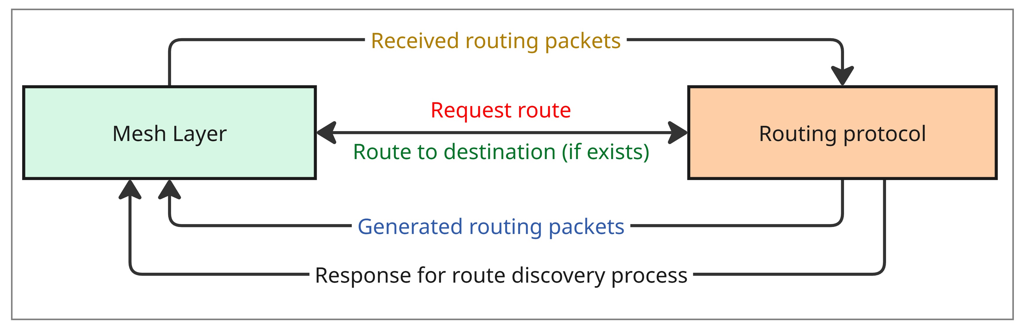
The hTDMANodeMesh helper object implements the mesh routing layer and includes the routing protocol. The mesh layer performs these functions.
On the transmitter side, the mesh layer makes a request to the routing protocol module for a route to the destination.
If a route exists, it forwards the packet to the MAC layer.
If a route does not exist, it queues the packet and waits until the routing protocol module discovers a route.
The mesh layer uses a dynamic routing protocol to establish routes between sources and destinations. You can also configure fixed routes. If you disable dynamic routing and do not configure fixed routes, the helper object sends all application packets directly to the MAC layer, assuming the destination lies one hop away. This example disables dynamic routing and configures no fixed routes, so the network effectively operates as a single-hop topology.
On the receiver side, the mesh layer receives a packet from the MAC layer. If the node is the destination, it forwards the packet to the application. If the node acts as a relay, it checks for an existing route to the destination.
If a route exists, it forwards the packet to the MAC layer.
If a route does not exist, it queues the packet until the routing protocol module finds a route.
This figure shows how the mesh layer communicates with the routing protocol to manage dynamic route discovery.
MAC
The hTDMANodeMAC helper object implements the MAC layer, which performs these functions.
The MAC layer stores packets from the mesh layer in separate priority queues. It dedicates one queue exclusively to routing packets, which hold higher priority than data packets.
On the transmitter side, when a node reaches its transmission slot, the MAC layer selects the highest priority non‑empty queue. It dequeues a packet, converts it into a MAC protocol data unit (PDU), and forwards it to the PHY.
On the receiver side, the MAC layer receives an indication from the PHY alongside the packet.
If the indication from PHY denotes successful packet reception and the node is either the intended destination of the packet or lies along its routing path, the MAC layer delivers the packet to the mesh layer.
Otherwise, the MAC layer discards the packet.
PHY
The hTDMANodePHY helper object implements an abstracted PHY, which performs these functions.
On the transmitter side, the PHY converts the MAC protocol Data Unit (MAC PDU) into an abstract PHY packet. The PHY transmits the packet in the designated TDMA slot.
On the receiver side, the PHY continuously listens for signals during every non-transmission slot of the node. It selects the strongest signal as the signal of interest (SOI) and calculates the signal-to-noise-plus-interference ratio (SINR) by treating all other signals as interference. Assuming binary phase-shift keying (BPSK) modulation, the PHY computes the bit error rate (BER) from the SINR. It derives the packet error probability from the BER. It indicates to MAC layer whether packet reception was successful or not along with the packet.
Assumptions
The example makes these assumptions.
The nodes transmit either data or routing packets in every slot of the TDMA frame. Routing packets take priority over data packets. The example does not include control slots for network management.
The example assigns slots to nodes statically, but you can configure these assignments as required.
Each node uses the entire channel bandwidth during its designated slot in a single-channel TDMA scheme.
The simulation excludes the transmission control protocol/internet protocol (TCP/IP) stack.
The example does not account for propagation delay or clock drift.
Each node uses a single-input single-output (SISO) antenna configuration.
Create and Configure MANET Scenario
Set the seed for the random number generator to 1 to ensure repeatability. The seed value controls the pattern of random number generation. The random number generated by the seed value impacts several processes within the simulation, including predicting packet reception success at the physical layer. To improve the accuracy of your simulation results after running the simulation, you can change the seed value, run the simulation again, and average the results over multiple simulations.
rng(1,"combRecursive")Specify the simulation time in seconds. Initialize the wireless network simulator.
simulationTime = 10;
networkSimulator = wirelessNetworkSimulator.init;
10;
networkSimulator = wirelessNetworkSimulator.init;TDMA Nodes
Specify the total number of TDMA nodes. Place the nodes randomly in a 1000-by-1000 square meter area.
numNodes = 8;
position = randi([0 1000],numNodes,3);
8;
position = randi([0 1000],numNodes,3);Specify the names of the nodes. Create the TDMA nodes by specifying their transmit power (in dBm), receiver gain (in dB), carrier frequency (in Hz), channel bandwidth (in Hz), and PHY data rate (in bps). To run the nodes as single-hop network, specify EnableDynamicRouting as false, and do not configure fixed routes.
names = "Node-" +(1:size(position,1));
nodes = hTDMANode(Name=names,Position=position, ...
    TransmitPower=10,ReceiveGain=5, ...
    CarrierFrequency=3e9,ChannelBandwidth=15e6, ...
    PHYDataRate=10e6,EnableDynamicRouting=false);
The hTDMAConfig helper object enables you to set the TDMA frame configuration by specifying the number of slots per frame, the slot duration, and the guard duration.
Install the TDMA configuration on nodes by using the configureTDMA object function of the hTDMANode helper object.
tdmaConfig = hTDMAConfig(NumSlotsPerFrame=numNodes, ...
    SlotDuration=1e-3,GuardDuration=0);                 % Slot duration and guard duration are in seconds
configureTDMA(nodes,tdmaConfig)
Assign Transmission Slots to Nodes
Use the assignSlot object function of the hTDMANode helper object to assign transmission slots to the nodes for sending data traffic. Assign one slot to each node so that the node at index i in the node array receives the slot at index i in the TDMA frame.
assignSlot(nodes)
You can alternatively use the slot-bitmap-based signature of the assignSlot object function of the hTDMANode helper object to perform custom slot assignment. For more information, see Further Exploration.
Add Mobility to Nodes
Add random waypoint mobility to the nodes by using the addMobility function of the hTDMANode helper object. You can also configure other mobility models such as constant velocity and random walk mobility models.
addMobility(nodes,SpeedRange=[5 10],BoundaryShape="rectangle",Bounds=[0 0 2000 2000],RefreshInterval=1)Add Application Traffic to Nodes
To create an On-Off application traffic pattern, use the networkTrafficOnOff object. Configure the On-Off application traffic pattern by specifying the application data rate in kbps. To install the application traffic on the nodes, use the addTrafficSource object function of the hTDMANode helper object . Note that the hTDMANode helper object does not support packet aggregation and packet segmentation. Therefore, the example makes these assumptions.
The
hTDMANodehelper object automatically configures the application packet size to fully utilize the slot duration for transmitting a single packet, accounting for the PHY data rate and protocol overheads.The protocol overheads consist of PHY overhead (4 bytes) and MAC overhead (15 bytes). This configuration enables you to transmit one application packet per slot without requiring packet segmentation or aggregation.
This equation calculates the application payload capacity of a slot.
Application payload capacity of slot (in bytes) = ((PHYDataRate*(SlotDuration - GuardDuration))/8) - (PHYOverheadInBytes + MACOverheadInBytes)
Install application traffic such that the node at index i sends data to the node at index i+1, with the last node sending data to the first node.
trafficDestinations = [nodes(2:end) nodes(1)];
appDataRate = randi([1200 1400],numNodes,1);                                     % In kilobits per second
for nodeIdx = 1:numNodes
    % Install traffic at the source node
    traffic = networkTrafficOnOff(DataRate=appDataRate(nodeIdx),OnTime=Inf,OffTime=0);
    addTrafficSource(nodes(nodeIdx),traffic,DestinationNode=trafficDestinations(nodeIdx))
end
Visualization
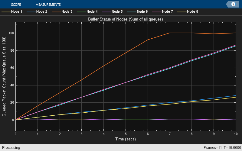
To visualize state transition for the nodes as they transmit and receive packets, set enablePacketVisualization to true. To view the live network topology, set enableNetworkVisualization to true. To visualize the live queued packet count in the transmit buffer of nodes, set enableMetricVisualization to true.
enablePacketVisualization =true; enableNetworkVisualization =
true; enableMetricVisualization =
true;
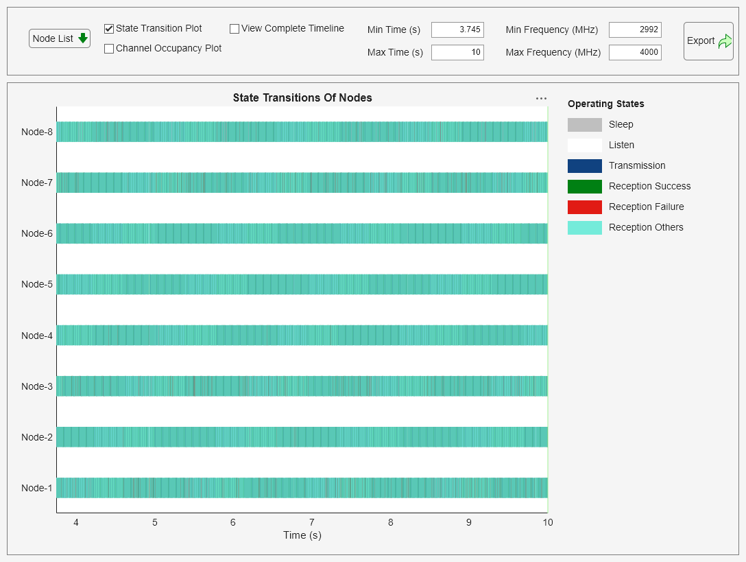
Visualize the state transition at the nodes by using the wirelessTrafficViewer object.
if enablePacketVisualization
    packetVisObj = wirelessTrafficViewer(ViewType="state-transition-plot",RefreshRate=5);
    addNodes(packetVisObj,nodes)
    hRegisterTDMAToTrafficViewer(packetVisObj,nodes)
end
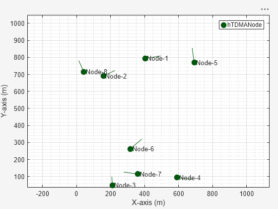
Visualize the network topology by using the wirelessNetworkViewer object.
if enableNetworkVisualization
    visualizerObj = wirelessNetworkViewer(RefreshRate=1);
    addNodes(visualizerObj,nodes)
end
Visualize the run-time visualization of the queued packet count in the transmit buffer of the nodes by using the helperMetricsVisualizer helper object.
if enableMetricVisualization
    metricsVisObj = helperMetricsVisualizer(nodes,RefreshRate=1);
end
Simulation and Results
Add the nodes to the wireless network simulator.
addNodes(networkSimulator,nodes)
To calculate the throughput, PDR, and average end-to-end delay of the network, use the helperTDMAKPIManager helper object.
performanceObj = helperTDMAKPIManager(nodes,["app-throughput","app-packet-delivery-ratio","app-average-end-to-end-delay","routing-overhead"],LogInterval=1);
Run the simulation for the specified simulation time.
run(networkSimulator,simulationTime)
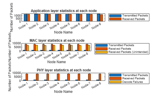
Retrieve the APP, MAC, and PHY statistics at each node by using the statistics object function of the hTDMANode helper object.
stats = statistics(nodes);
Calculate the throughput, PDR, and average end-to-end delay of the network.
Network throughput measures the rate at which the source nodes successfully delivers application data bytes to their destination nodes per unit time. Units are in Mbps.
networkThroughput = kpi(performanceObj,[],[],"app-throughput")networkThroughput = 9.7850
Packet delivery ratio is the ratio of application data packets successfully delivered at the destination nodes to the total number of application data packets transmitted by the source nodes.
pdr = kpi(performanceObj,[],[],"app-packet-delivery-ratio")pdr = 0.9630
Average end-to-end delay is the average time it takes for a data packet to travel from the source node to the destination node across the network in seconds.
avgEndToEndDelay = kpi(performanceObj,[],[],"app-average-end-to-end-delay")avgEndToEndDelay = 0.1729
Visualize these statistics at the APP, MAC and PHY.
Transmitted and received packets at APP.
Transmitted, received, and dropped packets at the MAC layer. The MAC layer drops any received packet from the PHY if node is not the intended receiver.
Transmitted, received, and failed packets at the PHY.
helperStatisticsVisualizer(nodes);
Further Exploration
You can use this example to further explore these functionalities.
Customize Transmission Slot Assignment
By default, the assignSlot object function of the hTDMANode helper object assigns one slot to each node such that the node at index i in the node array gets the slot at index i in the TDMA frame. You can customize transmission slot assignment by using the assignSlot object function.
Uncomment this code and add it in the Assign Transmission Slots to Nodes section to assign multiple custom slots in any order to the nodes.
% tdmaConfig.NumSlotsPerFrame = 10;                               % Set the number of slots to 10
% configureTDMA(nodes,tdmaConfig)                                 % Set the TDMA configuration
% slotBitmap = zeros(length(nodes),tdmaConfig.NumSlotsPerFrame);
% slotBitmap(1,[1 5]) = 1;                                       % Node 1 gets slot 1 and slot 5
% slotBitmap(2,[2 4]) = 1;                                       % Node 2 gets slot 2 and slot 4
% slotBitmap(3,3) = 1;                                           % Node 3 gets slot 3
% slotBitmap(4,7) = 1;                                           % Node 4 gets slot 7
% slotBitmap(5,10) = 1;                                          % Node 5 gets slot 10
% slotBitmap(6,8) = 1;                                           % Node 6 gets slot 8
% slotBitmap(7,9) = 1;                                           % Node 7 gets slot 9
% slotBitmap(8,6) = 1;                                           % Node 8 gets slot 6
% assignSlot(nodes,slotBitmap)                                   % Assign slots to nodes
Customize PHY Packet Error Modeling
By default, the example uses SINR to compute the packet error probability. You can override this behavior by defining custom logic to determine packet decoding success or failure. Pass the handle of your custom logic function to the nodes by using the PacketReceptionErrorFunction name-value argument in the node's constructor.
This code implements a custom packet error modeling function.
function decodeStatus = decodePHYPacket(packet,sinr)
% Check whether the received packet is a success or failure based on the
% SINR (in dB) of the packet

    % Check if the SINR of the packet is more than 15
    if sinr > 15
        % Consider the packet as decoded successfully
        decodeStatus = 0;
    else
        % Consider the packet as not decoded successfully
        decodeStatus = -1;
    end
end
To register the custom packet error modeling function decodePHYPacket with a TDMA node, uncomment this code and add it in the TDMA Nodes section.
% tdmaNode = hTDMANode(PacketReceptionErrorFunction=@decodePHYPacket);Model Priority-Based Traffic
You can specify the priority of application traffic you add to a TDMA node by using the addTrafficSource object function of the hTDMANode helper object. You can analyze the performance of traffic with a specified priority by getting the per-priority statistics at the MAC layer. By default, the priority for the traffic added using the addTrafficSource object function is 1.
To specify the priority for the application traffic added using the addTrafficSource object function, uncomment this code and add it in the Add Application Traffic to Nodes section.
% addTrafficSource(sourceNode,trafficSource,DestinationNode=destinationNode,Priority=1) % Priority of the traffic is 1
% addTrafficSource(sourceNode,trafficSource,DestinationNode=destinationNode,Priority=3) % Priority of the traffic is 3
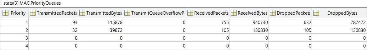
To retrieve the per-priority queue statistics in addition to the default node statistics, uncomment this code. You can see the per-priority queue statistics in the sample screenshot.
% stats = statistics(nodes,"all");
% statsMACNode3 = stats(3).MAC;
% disp(statsMACNode3.PriorityQueues) % Displays per-priority queue stats of node 3
Customize Logic to Serve Queued Traffic in Transmit Slot
By default, this example dequeues the packet from higher priority non-empty queues. You can customize this logic by modifying the selectQueueForTransmission object function of the hTDMANodeMAC helper object.
Model Packet Interference
You can model packet interference by assigning conflicting slots to nodes by using the assignSlot object function of the hTDMANode helper object. For more information, see Assign Transmission Slots to Nodes.
Customize Channel Model
By default, this example uses a channel model that accounts for FSPL. You can replace this default channel model with a custom channel model. For information about how to add a custom channel model, see Plug Custom Channel into Wireless Network Simulator.
Configure Broadcast Traffic
By default, this example implements unicast traffic. Add a broadcast traffic source by using the addTrafficSource object function of the hTDMANode helper object without specifying the DestinationNode argument.
To install a broadcast traffic source on a node, uncomment this code and add it in the Add Application Traffic to Nodes section.
% addTrafficSource(sourceNode,trafficSource)Supporting Functions
The example uses these helpers:
hTDMANode— Creates a TDMA nodehTDMAConfig— Creates a TDMA frame configuration objecthTDMANodeMesh— Implements mesh layer functionalityhTDMANodeMAC— Implements TDMA-based MAC functionalityhTDMANodePHY— Implements TDMA-based PHY functionalityhIntraNodeScheduler— Performs the scheduled operations of the nodehelperPacketDuplicateDetector— Detects duplicate packetshAODVRouting— Implements the AODV routing protocolhTDMANodeEventCallback— Invokes registered callbacks for the eventshelperTDMAKPIManager— Computes key performance indicators (KPI) of the TDMA networkhelperMetricsVisualizer— Plots MAC layer metricshelperStatisticsVisualizer— Plots the APP, MAC, and PHY statistics of each node
References
[1] 3GPP TR 36.814. "Evolved Universal Terrestrial Radio Access (E-UTRA). Further advancements for E-UTRA physical layer aspects". Release 15. 3rd Generation Partnership Project; Technical Specification Group Radio Access Network.
[2] 3GPP TR 36.814. "Feasibility Study on Licensed-Assisted Access to Unlicensed Spectrum". Release 13. 3rd Generation Partnership Project; Technical Specification Group Radio Access Network
[3] IEEE® 802.11™-14/0571r12. "11ax Evaluation Methodology." IEEE P802.11. Wireless LANs. https://www.ieee.org.
See Also
Objects
wirelessNetworkSimulator|wirelessTrafficViewer|wirelessNetworkViewer|networkTrafficOnOff|nodeMobilityRandomWalk|nodeMobilityRandomWaypoint|nodeMobilityConstantVelocity