802.11ax Multinode System-Level Simulation of Residential Scenario
This example shows how to simulate and evaluate the performance of an IEEE® 802.11ax™ (Wi-Fi® 6) [1] network in a residential scenario.
Using this example, you can:
Create and configure a residential scenario consisting of a building with three floors.
Create and configure a 802.11ax network in the residential scenario consisting of 12 access points (APs) and 24 stations (STAs)
Add full buffer traffic and TGax residential propagation model between the nodes.
Simulate the residential scenario by switching between the abstracted and full models of medium access control (MAC) and physical layer (PHY) and capture the network related statistics.
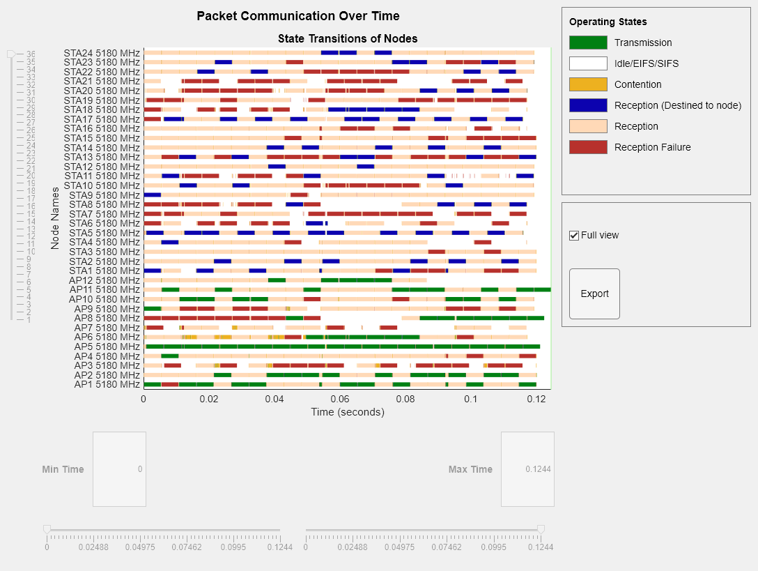
Visualize a state transition plot showing the time spent by the nodes in the Idle, Contention, Transmission, and Reception states.
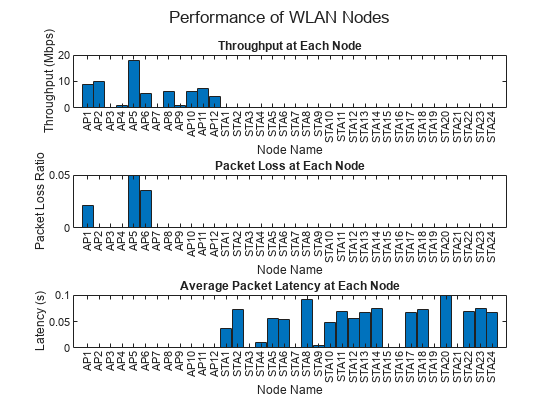
Visualize the node performance metrics such as MAC throughput, MAC packet loss, and application latency.
The simulation results show performance metrics such as MAC throughput, MAC packet loss, and application latency.
Additionally, you can use this example script to perform these tasks.
Residential Scenario
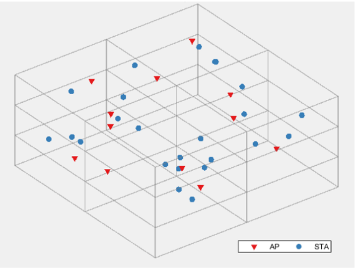
This example demonstrates a system-level simulation to evaluate the performance of an 802.11ax network in a residential scenario. The residential scenario consists of a building with three floors. These are the characteristics of the residential scenario:
The spacing between the floors is three meters.
Each floor consists of four rooms, and the dimensions of each room are 10-by-10-by-3 meters.
Each room has an AP and two STAs placed at random x- and y-locations at a height of 1.5 meters from the floor.
Each AP transmits data to the associated STAs in the same room.
The simulation scenario specifies a path loss model based on the distance between the nodes, and the number of walls and floors traversed by the WLAN signal. This figure shows the residential scenario simulated in this example.
To confirm compliance with the IEEE 802.11 standard [2], the features in this example are validated with Box-3 and Box-5 scenarios specified in the TGax evaluation methodology [4]. The network throughputs that are calculated for TGax simulation scenarios [5] are validated against the published calibration results from the TGax Task Group.
Check for Support Package Installation
Check if the Communications Toolbox™ Wireless Network Simulation Library support package is installed. If the support package is not installed, MATLAB® returns an error with a link to download and install the support package.
wirelessnetworkSupportPackageCheck
Configuration Parameters
Simulation Parameters
Set the seed for the random number generator to 1. The seed value controls the pattern of random number generation. The random number generated by the seed value impacts several processes within the simulation, including backoff counter selection at the MAC layer and predicting packet reception success at the PHY layer. To improve the accuracy of your simulation results after running the simulation, you can change the seed value, run the simulation again, and average the results over multiple simulations.
rng(1,"combRecursive")Specify the simulation time in seconds. To visualize a live state transition plot for all of the nodes, set the enablePacketVisualization variable to true. To view the node performance visualization, set the enableNodePerformancePlot variable to true.
simulationTime =0.12; enablePacketVisualization =
true; enableNodePerformancePlot =
true;
This example uses the abstract models of MAC and PHY layers at all the nodes (APs and STAs) by default. To use the full MAC layer model, set the macabstraction variable to false. Similarly, to use the full PHY layer model, set the phyabstraction variable to none. For more information about MAC and PHY, see the Get Started with WLAN System-Level Simulation in MATLAB example.
macabstraction =true; phyabstraction =
"tgax-evaluation-methodology";
Residential Scenario Parameters
The ScenarioParameters structure defines the size and layout of the residential building by using these parameters.
BuildingLayout— Specify the number of rooms along the length, breadth, and height of the building.RoomSize— Specify the size of each room in meters.NumRxPerRoom— Specify the number of stations per room.
The example assumes each room contains one transmitting AP and two receiving STAs.
ScenarioParameters = struct;
ScenarioParameters.BuildingLayout = [2 2 3];
ScenarioParameters.RoomSize = [10 10 3];
ScenarioParameters.NumRxPerRoom = 2;
Configure WLAN Scenario
Initialize the wireless network simulator by using the wirelessNetworkSimulator object.
networkSimulator = wirelessNetworkSimulator.init;
Nodes
The example creates a residential scenario consisting of 36 nodes. Node 1 to Node 12 are APs, and Node 13 to Node 36 are STAs. The hGetIDsAndPositions helper function returns node IDs and random positions for the AP and STAs within each room. The function returns an array, nodeIDs, where each row stores the IDs of the AP and its associated STAs in the same room. The apPositions and staPositions outputs contain the x-, y-, and z-Cartesian coordinates of the APs and STAs, respectively. Units are in meters.
[nodeIDs,apPositions,staPositions] = hGetIDsAndPositions(ScenarioParameters);
The wlanDeviceConfig object enables you to set the configuration parameters for the APs and STAs. Create two wlanDeviceConfig objects to initialize the configuration parameters for the APs and the STAs. Specify the operating mode, modulation and coding scheme, and the transmission power (in dBm) for the APs and STAs.
accessPointCfg = wlanDeviceConfig(Mode="AP",MCS=2,TransmitPower=15);    % AP device configuration
stationCfg = wlanDeviceConfig(Mode="STA",MCS=2,TransmitPower=15);       % STA device configuration
Create two arrays of wlanNode objects, corresponding to the AP nodes and STA nodes, by specifying their Position properties as apPosition and staPosition, respectively. Each array contains a number of objects equal to the number of positions specified by the corresponding value. Specify the Name, DeviceConfig, PHYAbstractionMethod, and MACFrameAbstraction properties of wlanNode objects.
accessPoints = wlanNode(Position=apPositions, ...
    Name="AP"+(1:size(apPositions,1)), ...
    DeviceConfig=accessPointCfg, ...
    PHYAbstractionMethod=phyabstraction, ...
    MACFrameAbstraction=macabstraction);
stations = wlanNode(Position=staPositions, ...
    Name="STA"+(1:size(staPositions,1)), ...
    DeviceConfig=stationCfg, ...
    PHYAbstractionMethod=phyabstraction, ...
    MACFrameAbstraction=macabstraction);
Create a WLAN network consisting of APs and STAs.
nodes = [accessPoints stations];
To ensure all the nodes are configured properly, use the hCheckWLANNodesConfiguration helper function.
hCheckWLANNodesConfiguration(nodes)
Association and Application Traffic
Associate the STAs in each room to the corresponding AP by using the associateStations object function of the wlanNode object. Configure the APs with continuous application traffic to their associated STAs by using the FullBufferTraffic argument.
numAPs = prod(ScenarioParameters.BuildingLayout);                                         % One AP per room
for apID = 1:numAPs
    associateStations(nodes(apID),[nodes(nodeIDs(apID,2:end))],FullBufferTraffic="DL");
end
Create Network
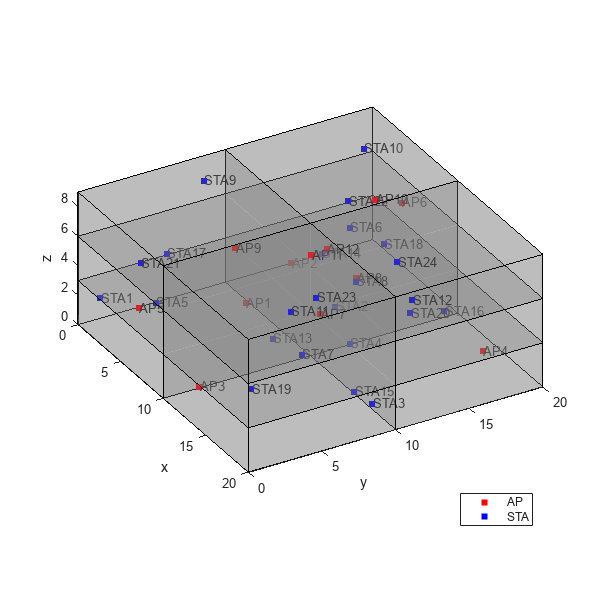
Create transmitter and receiver sites from the node configurations by using the hCreateSitesFromNodes helper function. Create the building geometry from the residential scenario parameters by using the hTGaxResidentialTriangulation helper object. Visualize the residential building along with the transmitter and receiver sites by using the hVisualizeScenario helper function.
[txSites,rxSites] = hCreateSitesFromNodes(nodes);
triangulationObj = hTGaxResidentialTriangulation(ScenarioParameters);
hVisualizeScenario(triangulationObj,txSites,rxSites,apPositions)
Wireless Channel
This example uses the TGax residential propagation model to determine path loss between nodes. Path loss is a function of the number of walls, number of floors, and distance between nodes. Create a path loss model by using the hTGaxResidentialPathLoss helper function. Obtain the path loss function handle by using the hCreatePathlossTable helper function.
propModel = hTGaxResidentialPathLoss(Triangulation=triangulationObj,ShadowSigma=0,FacesPerWall=1);
[~,pathLossFcn] = hCreatePathlossTable(txSites,rxSites,propModel);
To add a channel object to the wireless network simulator, create a hSLSTGaxMultiFrequencySystemChannel helper object by using the path loss function handle. Add the residential path loss model to the network simulator by using the addChannelModel object function of the wirelessNetworkSimulator object.
channel = hSLSTGaxMultiFrequencySystemChannel(nodes,PathLossModel="custom",PathLossModelFcn=pathLossFcn);
addChannelModel(networkSimulator,channel.ChannelFcn)
Simulation and Results
Add the nodes to the wireless network simulator.
addNodes(networkSimulator,nodes)
To view the state transition plot, use the helperPlotPacketTransitions helper object. To disable the packet communication over frequency subplot, set the FrequencyPlotFlag property of helperPlotPacketTransitions helper object to false.
if enablePacketVisualization
    packetVisObj = helperPlotPacketTransitions(nodes,simulationTime,FrequencyPlotFlag=false);
end
To view the node performance visualization, use the helperPerformanceViewer helper object.
perfViewerObj = helperPerformanceViewer(nodes,simulationTime);
Run the network simulation for the specified simulation time. The runtime visualization shows the time spent by the AP and the STA in Idle, Contention, Transmission, and Reception state.
run(networkSimulator,simulationTime);
The plotNetworkStats object function displays these simulation plots.
MAC throughput (in Mbps) at each transmitter node (APs).
MAC packet loss ratio (ratio of unsuccessful data transmissions to the total data transmissions) at each transmitter node (APs).
Average application packet latency incurred at each receiver node (STAs). The average application packet latency shows the average latency that each STA incurs to receive the downlink traffic from the AP.
if enableNodePerformancePlot
    plotNetworkStats(perfViewerObj);
end
Retrieve the APP, MAC, and PHY statistics at each node by using the statistics object function of the wlanNode object.
stats = statistics(nodes);
Further Exploration
You can use this example to further explore these functionalities.
Configure IEEE 802.11be Compliant Frame Transmissions
To configure IEEE 802.11be [3] compliant frame transmissions, you can:
Specify the PHY transmission format of the WLAN device as
"EHT-SU".Specify the modulation and coding scheme (MCS) of the WLAN device as an integer in the range
[0,13].
For more information on TransmissionFormat and MCS properties, see the wlanDeviceConfig object.
Export WLAN MAC Frames to PCAP or PCAPNG File
You can capture packets at both AP and STA nodes by using the hExportWLANPackets helper object. Specify the node objects at which you want to capture the packets. To capture packets at multiple nodes, specify the corresponding node objects as an array. You can export the packets captured at the AP and STA nodes to a PCAP or PCAPNG file. For more information about capturing packets, and exporting captured packets to a PCAP or PCAPNG file, see the Get Started with WLAN System-Level Simulation in MATLAB example.
Appendix
The example uses these helpers:
hGetIDsAndPositions— Return node IDs and random positions for the APs and STAshCheckWLANNodesConfiguration— Check if the node parameters are configured correctlyhCreateSitesFromNodes— Return transmitter and receiver siteshTGaxResidentialTriangulation— Create the residential scenario geometryhCreatePathlossTable— Return the path loss function handle in the residential scenariohVisualizeScenario— Display the residential building along with transmitters and receivershTGaxIndoorLinkInfo— Return the number of floors, the number of walls, and the distance between points for a linkhExportWLANPackets— Capture MAC frames and write them into a PCAP or PCAPNG filehTGaxResidentialPathLoss— Configure and create a residential path loss modelhSLSTGaxMultiFrequencySystemChannel— Return a system channel object and set the path loss modelhSLSTGaxAbstractSystemChannel— Return a channel object for an abstracted PHY layerhSLSTGaxSystemChannel— Return a channel object for a full PHY layerhSLSTGaxSystemChannelBase— Return the base channel objecthelperPlotPacketTransitions— Plot the state transition figurehelperPerformanceViewer
References
"IEEE Standard for Information Technology--Telecommunications and Information Exchange between Systems Local and Metropolitan Area Networks--Specific Requirements Part 11: Wireless LAN Medium Access Control (MAC) and Physical Layer (PHY) Specifications Amendment 1: Enhancements for High-Efficiency WLAN." IEEE. https://doi.org/10.1109/IEEESTD.2021.9442429.
"IEEE Standard for Information Technology--Telecommunications and Information Exchange between Systems - Local and Metropolitan Area Networks--Specific Requirements Part 11: Wireless LAN Medium Access Control (MAC) and Physical Layer (PHY) Specifications." IEEE. https://doi.org/10.1109/IEEESTD.2021.9363693.
“IEEE Draft Standard for Information Technology–Telecommunications and Information Exchange between Systems Local and Metropolitan Area Networks–Specific Requirements - Part 11: Wireless LAN Medium Access Control (MAC) and Physical Layer (PHY) Specifications Amendment: Enhancements for Extremely High Throughput (EHT).” IEEE P802.11be/D5.0, November 2023, January 2024, 1–1045. https://ieeexplore.ieee.org/document/10381585.
IEEE P802.11 Wireless LANs - 11ax Evaluation Methodology. IEEE 802.11-14/0571r12. IEEE, January 2016.
IEEE P802.11 Wireless LANs - TGax Simulation Scenarios. IEEE 802.11-14/0980r16. IEEE, July 2015.