SNR Definition in End-to-End Simulations
This example shows how WLAN Toolbox™ defines signal-to-noise ratio (SNR) in end-to-end simulations.
SNR Definition
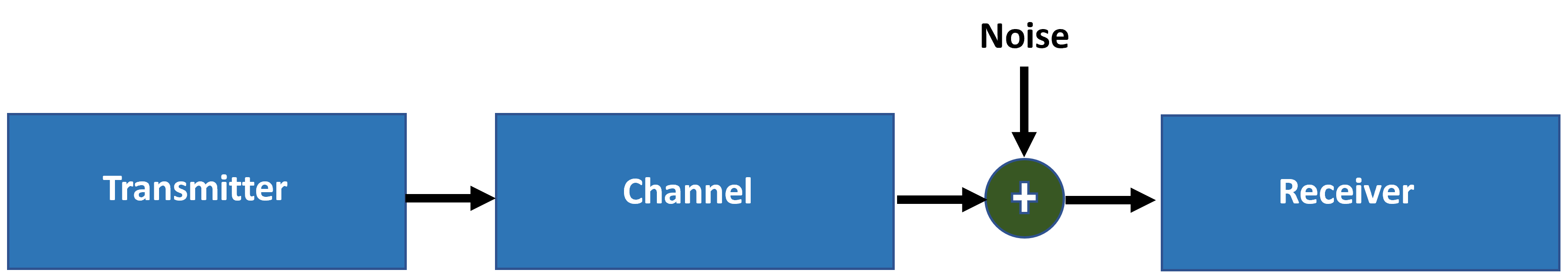
WLAN Toolbox™ end-to-end simulation examples introduce AWGN to the received signal in the time domain, after the fading channel, and before OFDM demodulation.
WLAN Toolbox defines the SNR as the expected SNR per subcarrier (SC) per receive antenna. In IEEE Std 802.11-2020 [1], the transmitter normalizes the waveform, so that the sum of the baseband power over all transmit antennas is 1 W.
The expected SNR per subcarrier (SC) is denoted by .
and are the average signal and noise power per subcarrier per receive antenna, respectively. models the AWGN that is added to the signal.
For a signal with discrete Fourier transform (DFT) , Parseval's theorem states
.
is the FFT length. Divide the equation by to get the average signal power
.
In WLAN, the signal of interest does not use all FFT bins (or subcarriers) because of guard bands. If the signal uses only subcarriers of the FFT, the signal power is
. (1)
is the number of nonzero power subcarriers per OFDM symbol.
The signal power per subcarrier is
.
The noise power per subcarrier is
.
Because the noise is added in the time domain, the noise occupies all subcarriers, not just the allocated subcarriers. Therefore, the noise power, N, is divided by and not .
With these definitions, the becomes
. (2)
Rearranging equation 2, the noise power at the input of an OFDM demodulator is
. (3)
The awgn function adds noise in the time domain. If you use equation 1 and equation 3, the time-domain SNR becomes
.
is in decibels. The in decibels is
. (4)
SNR Verification
To verify your target SNR, you need to understand the process that WLAN Toolbox uses to simulate an end-to-end link for the given SNR. For this example, WLAN Toolbox simulates an end-to-end link and measures the SNR of the received packet as shown in the figure below. Multiple packets are transmitted through a Fourier channel. A Fourier matrix in a MIMO system assumes that all receive antennas are coupled with the transmit antennas. The matrix is orthogonal, so the spatial streams are completely separate, resulting in no noise enhancement [2].
The example uses the demodulated L-LTF field with and without noise to estimate the noise and signal power of each packet, and hence, the SNR. The example displays the simulated SNR, which is averaged over multiple packets.
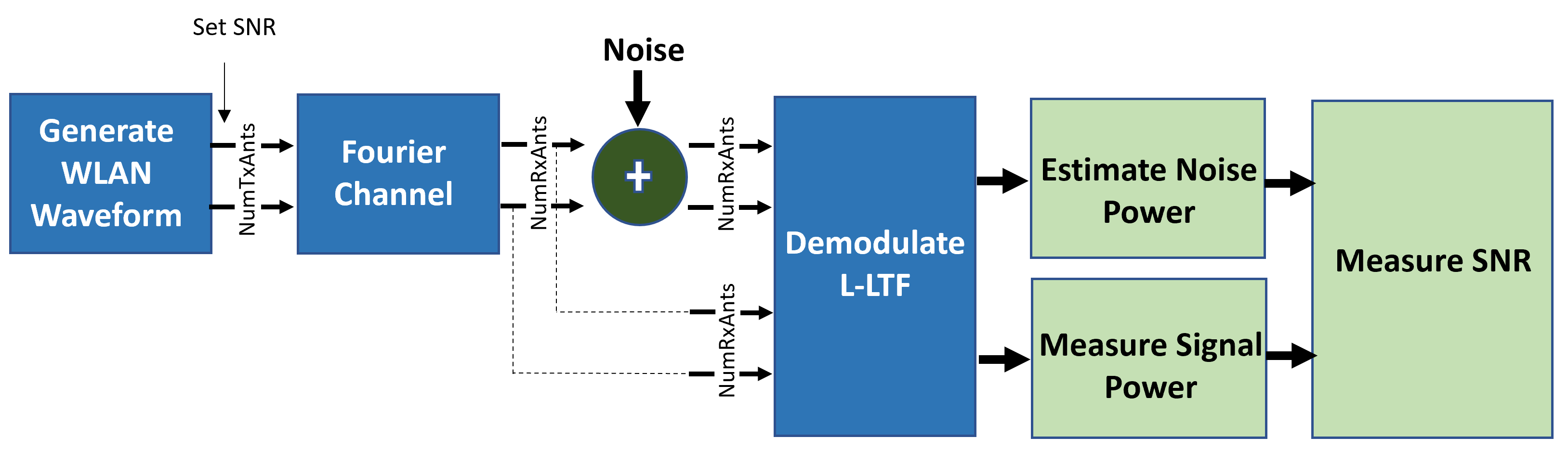
For each packet, the following steps occur in the process:
Generate a non-HT waveform.
Set the required SNR according to Equation-4.
Pass the waveform through a Fourier channel.
Add AWGN to the received waveform to create the desired average SNR per subcarrier after OFDM demodulation.
Extract and OFDM-demodulate the L-LTF field before and after adding noise.
Estimate the signal power by using the demodulated L-LTF symbols before adding noise.
Estimate the noise power by using the demodulated L-LTF symbols after adding noise.
Calculate and display the average SNR.
Simulation Setup
For this example specify a target SNR of 10 dB.
SNRSC = 10;
rng("default") % Set default random number generator for repeatability
Set the number of transmit and receive antennas.
nTxAnts = 2;
nRxAnts = 2;
Create a configuration object for a non-HT transmission.
cfg = wlanNonHTConfig;
cfg.NumTransmitAntennas = nTxAnts; % N transmit antennas
SNR Setup
Scale the SNR to account for energy in unused subcarriers according to equation 4.
ofdmInfo = wlanNonHTOFDMInfo('NonHT-Data',cfg); % Get the OFDM info
SNRdB = SNRSC-10*log10(ofdmInfo.FFTLength/ofdmInfo.NumTones);
Simulate Link
Now simulate the transmission and verify that the measured SNR approximates your target SNR.
% Indices for accessing each field within the time-domain packet
ind = wlanFieldIndices(cfg);
N = 100;
nVar = zeros(1,N);
signalPower = zeros(1,N);

for i=1:N
    % Generate a packet waveform
    txPSDU = randi([0 1],cfg.PSDULength*8,1); % PSDULength in bytes
    tx = wlanWaveformGenerator(txPSDU,cfg);

    % Channel
    h = dftmtx(max(nTxAnts,nRxAnts)); % Fourier channel
    h = h(1:nTxAnts,1:nRxAnts);
    rx = tx*h;

    % Add noise
    rxNoise = awgn(rx,SNRdB);

    % Measure noise power by comparing L-LTF over 2 symbols. The noise
    % power is averaged across receive antennas.
    lltf = rxNoise(ind.LLTF(1):ind.LLTF(2),:);
    lltfDemod = wlanNonHTOFDMDemodulate(lltf,'L-LTF',cfg);
    nVar(i) = wlanLLTFNoiseEstimate(lltfDemod);

    % Measure signal power before noise addition
    lltf = rx(ind.LLTF(1):ind.LLTF(2),:);
    lltfDemod = wlanNonHTOFDMDemodulate(lltf,'L-LTF',cfg);
    signalPower(i) = mean(lltfDemod.*conj(lltfDemod),'all');
end

% Measure SNR
measuredSNR = signalPower./nVar;

% Verify that the measured SNR approximates the target SNR
disp(['Measured SNR ' num2str(10*log10(mean(measuredSNR))) ' dB'])
Measured SNR 10.0864 dB
References
IEEE Std 802.11 - 2020. Telecommunications and Information Exchange between Systems Local and Metropolitan Area Networks Specific Requirements.
Perahia, Eldad, and Robert Stacey. Next Generation Wireless LANS: 802.11n and 802.11ac. Cambridge University Press, 2013.