Wi-Fi 8 Packet Error Rate Simulation for Uplink Trigger-Based Format with DRUs
This example shows how to measure the packet error rate of an IEEE® 802.11bn™ (Wi-Fi® 8) ultra high-reliability (UHR) uplink trigger-based (TB) format with distributed resource units (DRUs).
Introduction
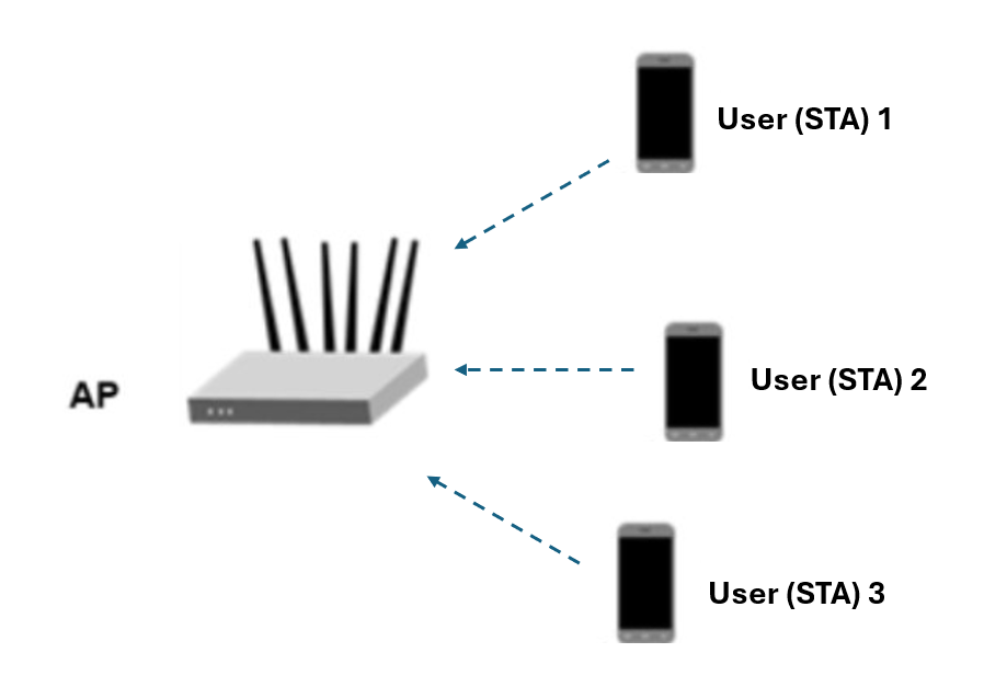
The 802.11bn [1] UHR trigger-based (UHR TB) format allows for OFDMA or MU-MIMO transmission in the uplink. The access point (AP) controls the UHR TB transmission and provides the required parameters to all participating stations (STAs) using a trigger frame. When triggered by the AP, each STA simultaneously transmits a UHR TB packet, as shown in this diagram.
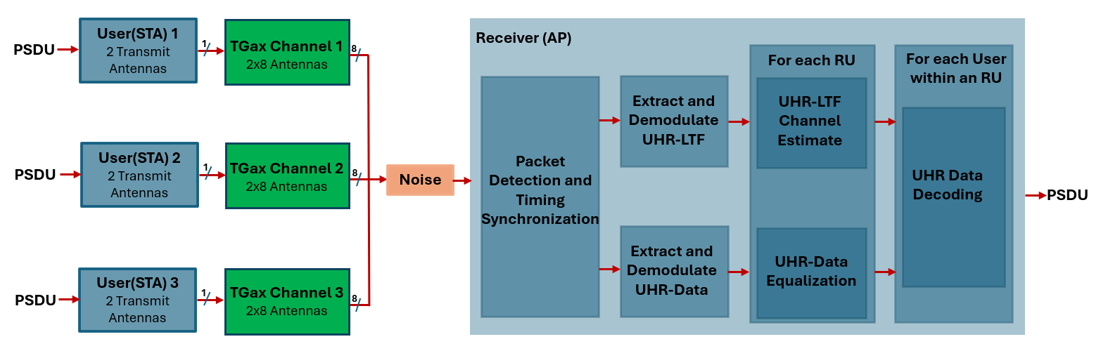
This example uses a link-level simulation to determine the packet error rate (PER) of a UHR TB link for three STAs in an MU-MIMO configuration. The transmitter sends multiple packets for each signal-to-noise ratio (SNR), with no impairments apart from channel and noise. The receiver demodulates the packets and recovers the PSDUs for each STA. The example compares the recovered PSDUs to the transmitted PSDUs to determine the number of packet errors, and hence, the packet error rate for all users. The receiver performs packet detection, timing synchronization, and symbol equalization. This example does not perform frequency offset correction. The UHR TB processing chain is shown in this diagram.
Distributed Resource Units
This example uses distributed resource units (DRUs), which are new to Wi-Fi 8. In a DRU, the tones that make up the RU are evenly spread across the whole bandwidth.
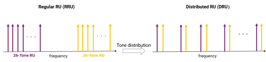
In earlier standards, RUs were required to consist of groups of adjacent tones. DRUs enable transmissions at a higher power level by reducing the number of tones per MHz while keeping the power spectral density the same.
User Configuration
This example configures the allocation and transmit parameters for multiple uplink STAs using a uhrTBSystemConfig object.
% DRUIndication indicates whether a DRU or an RRU transmission is solicited
% in each 80 MHz frequency subblock. DistributionBandwidth is a cell array
% for each 80 MHz frequency subblock indicating the distributed bandwidth
% as one of 20 MHz, 40 MHz, or, 80 MHz.
cfgSys =  uhrTBSystemConfig(25,DRUIndication=true,DistributionBandwidth={20}); % 20 MHz
In a trigger-based transmission, some parameters are the same for all uplink users, while some can differ. The User property of cfgSys contains a cell array of user configurations. Each element of the cell array is an object that sets the parameters of an individual user. In this example, all users have the same transmission parameters.
% These parameters are the same for all users in the MU-MIMO system
cfgSys.UHRLTFType = 4;      % UHR-LTF compression mode
cfgSys.GuardInterval = 3.2; % Guard interval type

% The individual parameters for each user are specified below
numUsers = numel(cfgSys.User); % Number of uplink users
for userIdx = 1:numUsers
    cfgSys.User{userIdx}.NumTransmitAntennas = 2;
    cfgSys.User{userIdx}.NumSpaceTimeStreams = 2;
    cfgSys.User{userIdx}.SpatialMapping = 'Direct';
    cfgSys.User{userIdx}.MCS = 7;
    cfgSys.User{userIdx}.APEPLength = 1e3;
    cfgSys.User{userIdx}.ChannelCoding = 'LDPC';
end
allocInfo = ruInfo(cfgSys);
Use a uhrTBConfig object to configure a trigger-based transmission for a single user within the system. The userConfig method configures the transmission for all users. This example creates a cell array of three UHR TB objects that describes the transmission of three users.
cfgTB = userConfig(cfgSys);
Simulation Parameters
For each SNR point (in dB) in the snr vector, the example generates the number of packets that you specify. The example passes the packets through a channel and demodulates them to determine the packet error rate.
snr = 18:2:22;
numRx = 8; % Number of receive (AP) antennas

% The sample rate and field indices for the UHR TB packet are the same for
% all users. Use the trigger configuration of the first user to get the
% sample rate and field indices of the UHR TB PPDU.
fs = wlanSampleRate(cfgTB{1}.ChannelBandwidth);    % Same for all users
ind = uhrFieldIndices(cfgTB{1}); % Same for all users
Channel Configuration
This example uses a TGax non-line-of-sight (NLOS) indoor channel model with delay profile Model-B. Model-B is in NLOS when the distance between the transmitter and receiver is greater than or equal to 5 meters. This is described further in wlanTGaxChannel. In this example all STAs are the same distance from the AP.
tgaxBase = wlanTGaxChannel;
tgaxBase.SampleRate = fs;
tgaxBase.TransmissionDirection = 'Uplink';
tgaxBase.TransmitReceiveDistance = 10;
chanBW = cfgSys.ChannelBandwidth;
tgaxBase.ChannelBandwidth = chanBW;
tgaxBase.NumReceiveAntennas = numRx;
tgaxBase.NormalizeChannelOutputs = false;
The example creates individual channels for each of the three users. Each channel is a copy of tgaxBase, but with a different UserIndex property. The channels are stored in the cell array tgax. The difference in the UserIndex properties of each individual channel provides a unique channel for each user. This example uses a random channel realization for each packet by randomly varying the UserIndex property for each transmitted packet.
% A cell array stores the channel objects, one per user
tgax = cell(1,numUsers);
for userIdx = 1:numUsers
    tgax{userIdx} = clone(tgaxBase);
    tgax{userIdx}.NumTransmitAntennas = cfgSys.User{userIdx}.NumTransmitAntennas;
    tgax{userIdx}.UserIndex = userIdx;
end
SNR Point Processing
For each SNR point, the example tests a number of packets and calculates the PER. The pre-UHR preamble of 802.11bn is backward-compatible with 802.11be™. Therefore, this example uses the timing synchronization components of an 802.11be waveform to synchronize the UHR waveform at the receiver. For each user, the example follows these processing steps to create a waveform that contains packets from all three users:
To create a UHR TB waveform, create and encode a PSDU for each user, based on predefined user parameters.
Pass the waveform for each user through an indoor TGax channel model. The randomly varying
UserIndexproperty of the channel creates different channel realizations for each user. This results in different spatial correlation properties for each user.Scale and combine the waveforms for all UHR TB users to ensure each user has the same SNR after the addition of noise.
Add AWGN to the received waveform. This step helps to achieve the desired average SNR per active subcarrier after OFDM demodulation.
The receiver follows these processing steps:
Detect the packet.
Perform fine timing synchronization. The legacy short training field (L-STF), legacy long training field (L-LTF), and legacy signaling field (L-SIG) samples provide fine timing to enable packet detection at the start or end of the L-STF.
Extract UHR-LTF and UHR-Data fields for all users after synchronization of the received waveform. OFDM-demodulate the UHR-LTF and UHR-Data fields.
Perform channel estimation on the demodulated UHR-LTF symbols for each DRU.
Perform noise estimation using the demodulated data field pilots for each DRU.
Extract and demodulate the data field and perform equalization for all users within a DRU.
Recover PSDU bits for each DRU and user within the DRU by demodulating and decoding the spatial streams for a user.
You can use a parfor loop to parallelize the processing of the SNR points. To enable the use of parallel computing for increased speed, comment out the for statement and uncomment the parfor statement below.
ofdmInfo = uhrOFDMInfo('UHR-Data',cfgTB{1});
numSNR = numel(snr); % Number of SNR points
numPackets = 50; % Number of packets to simulate
packetErrorRate = zeros(numSNR,numUsers);
txPSDU = cell(numUsers);

% parfor isnr = 1:numSNR % Use 'parfor' to speed up the simulation
for isnr = 1:numSNR
    % Create UHR TB object for receiver processing
    cfgUHRTB = uhrTBConfig;
    cfgUHRTB.ChannelBandwidth = cfgSys.ChannelBandwidth;
    cfgUHRTB.UHRLTFType = cfgSys.UHRLTFType;

    % Set random substream index per iteration to ensure that each
    % iteration uses a repeatable set of random numbers
    stream = RandStream('combRecursive',Seed=0);
    stream.Substream = isnr;
    RandStream.setGlobalStream(stream);

    % RU allocation information
    sysInfo = ruInfo(cfgSys);

    % Simulate multiple packets
    numPacketErrors = zeros(numUsers,1);
    for pktIdx = 1:numPackets

        % Transmit processing
        rxWaveform = 0;
        packetError = zeros(numUsers,1);
        txPSDU = cell(1,numUsers);

        % Generate random channel realization for each packet by varying
        % the UserIndex property of the channel. This assumes all users
        % have the same number of transmit antennas.
        chPermutations = randperm(numUsers);
        for userIdx = 1:numUsers
            % UHR TB config object for each user
            cfgUser = cfgTB{userIdx};

            % Generate a packet with random PSDU
            txPSDU{userIdx} = randi([0 1],psduLength(cfgUser)*8,1,'int8');

            % Generate UHR TB waveform, containing payload for single user
            txTrig = uhrWaveformGenerator(txPSDU{userIdx},cfgUser);

            % Pass waveform through a random TGax Channel
            channelIdx = chPermutations(userIdx);
            reset(tgax{channelIdx}); % New channel realization
            rxTrig = tgax{channelIdx}([txTrig; zeros(15,size(txTrig,2))]);

            % Scale the transmit power of the user within an RU. This is to
            % ensure the same SNR for each user after the addition of noise.
            ruNum = cfgSys.User{userIdx}.RUNumber;
            SF = sqrt(1/sysInfo.NumUsersPerRU(ruNum))*sqrt(sum(cfgUser.RUSize)/(sum(cell2mat(sysInfo.RUSizes))));

            % Combine uplink users into one waveform
            rxWaveform = rxWaveform+SF*rxTrig;
        end

        % Pass the waveform through AWGN channel. Account for noise energy
        % in nulls so the SNR is defined per active subcarriers.
        packetSNR = snr(isnr)-10*log10(ofdmInfo.FFTLength/(sum(cell2mat(sysInfo.RUSizes))));
        rxWaveform = awgn(rxWaveform,packetSNR);

        % Receive processing
        % Packet detect and determine coarse packet offset
        coarsePktOffset = wlanPacketDetect(rxWaveform,chanBW);
        if isempty(coarsePktOffset) % If empty no L-STF detected; packet error
            numPacketErrors = numPacketErrors+1;
            continue; % Go to next loop iteration
        end

        % Extract the non-HT fields and determine fine packet offset
        nonhtfields = rxWaveform(coarsePktOffset+(ind.LSTF(1):ind.LSIG(2)),:);
        finePktOffset = wlanSymbolTimingEstimate(nonhtfields,chanBW);

        % Determine final packet offset
        pktOffset = coarsePktOffset+finePktOffset;

        % If packet detected out with the range of expected delays from
        % the channel modeling; packet error
        if pktOffset>50
            numPacketErrors = numPacketErrors+1;
            continue; % Go to next loop iteration
        end

        % Extract UHR-LTF and UHR-Data fields for all RUs
        rxLTF = rxWaveform(pktOffset+(ind.UHRLTF(1):ind.UHRLTF(2)),:);
        rxData = rxWaveform(pktOffset+(ind.UHRData(1):ind.UHRData(2)),:);

        for ruIdx = 1:allocInfo.NumRUs
            userNumber = cfgSys.RU{ruIdx}.UserNumbers; % Same for all users
            cfgUserRef = cfgTB{userNumber(1)}; % Reference user configuration

            % Demodulate UHR-LTF and UHR-Data field
            demodLTFRU = uhrDemodulate(rxLTF,'UHR-LTF',cfgUserRef);
            demodDataRU = uhrDemodulate(rxData,'UHR-Data',cfgUserRef);

            % Configure the relevant properties in UHR TB object
            cfgUHRTB.RUSize = allocInfo.RUSizes{ruIdx};
            cfgUHRTB.RUIndex = allocInfo.RUIndices{ruIdx};
            cfgUHRTB.NumSpaceTimeStreams = allocInfo.NumSpaceTimeStreamsPerRU(ruIdx);
            cfgUHRTB.NumUHRLTFSymbols = numUHRLTFSymbols(cfgSys);
            cfgUHRTB.DRU = cfgUserRef.DRU;
            cfgUHRTB.DistributionBandwidth = cfgUserRef.DistributionBandwidth;

            % Channel estimate
            [chanEst,ssPilotEst] = uhrLTFChannelEstimate(demodLTFRU,cfgUHRTB);


            % Get indices of data and pilots within RU (without nulls)
            ruOFDMInfo = uhrOFDMInfo('UHR-Data',cfgUserRef);

            % Estimate noise power in UHR fields of each user
            nVarEst = uhrDataNoiseEstimate(demodDataRU(ruOFDMInfo.PilotIndices,:,:),ssPilotEst,cfgUserRef);

            % Discard pilot subcarriers
            demodDataSym = demodDataRU(ruOFDMInfo.DataIndices,:,:);
            chanEstData = chanEst(ruOFDMInfo.DataIndices,:,:);

            % Equalize
            [eqSym,csi] = uhrEqualize(demodDataSym,chanEstData,nVarEst,cfgUHRTB,'UHR-Data');

            for userIdx = 1:allocInfo.NumUsersPerRU(ruIdx)
                % Get TB config object for each user
                userNum = cfgSys.RU{ruIdx}.UserNumbers(userIdx); % User within an RU
                cfgUserTB = cfgTB{userNum};

                % Get space-time stream indices for the current user
                stsIdx = cfgUserTB.StartingSpaceTimeStream-1+(1:cfgUserTB.NumSpaceTimeStreams);

                % Demap and decode bits
                rxPSDU = uhrDataBitRecover(eqSym(:,:,stsIdx),nVarEst,csi(:,stsIdx),cfgUserTB);

                % PER calculation
                packetError(userNum) = any(biterr(txPSDU{userNum},rxPSDU));
            end
        end
        numPacketErrors = numPacketErrors+packetError;
    end

    % Calculate PER at SNR point
    packetErrorRate(isnr,:)= numPacketErrors/numPackets;
    disp(['SNR ' num2str(snr(isnr)) ' dB'...
       ' completed for ' num2str(numUsers) ' users']);

end
SNR 18 dB completed for 3 users
SNR 20 dB completed for 3 users
SNR 22 dB completed for 3 users
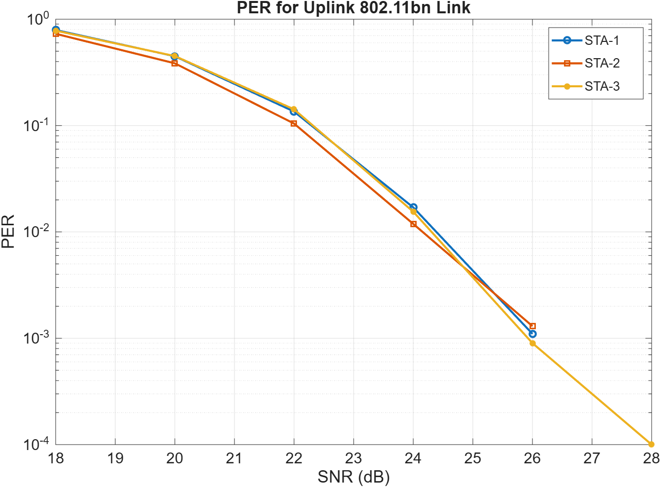
Packet Error Rate vs Signal to Noise Ratio
figure;
semilogy(repmat(snr.',1,numUsers),packetErrorRate);
ax = gca;
ax.LineStyleCyclingMethod = "withcolor";
ax.LineStyleOrder = ["-o"; "-s"; "-*";  "-+"];

grid on;
xlabel('SNR (dB)');
ylabel('PER');
dataStr = arrayfun(@(x)sprintf('STA-%d',x),1:numUsers,'UniformOutput',false);
legend(dataStr);
title('PER for Uplink 802.11bn Link');
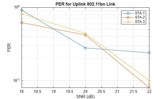
The numPackets parameter controls the number of packets at each SNR point. For meaningful results, set the parameter to a larger value than the one presented in this example. The figure below was created by running a longer simulation with numPackets=1e4 and snr=18:2:28.
References
[1] IEEE P802.11bn™/D1.0. Draft Standard for Information technology -Telecommunications and information exchange between systems Local and metropolitan area networks - Specific requirements. Part 11: Wireless LAN Medium Access Control (MAC) and Physical Layer (PHY) Specifications. Amendment 6: Enhancements for ultra-high reliability (UHR).