How to generate multiple output in Simulink with multiple input
显示 更早的评论
Recently, in order to get more familiar with simulink, I tried to establish some easy simulink model(figure shown in the following), however, there is a wierd bug. I inserted a sine wave with different amplitude, equivalently, two inputs into the matlab function block. Intuitively, this testbench should gives two output, but my workspace window only showed one ! so I want to consult what kind of consideration that I miss, thanks for you guys answer this question!(attatched file is the code of function block )
回答(1 个)
Vidhi Agarwal
2025-7-17
0 个投票
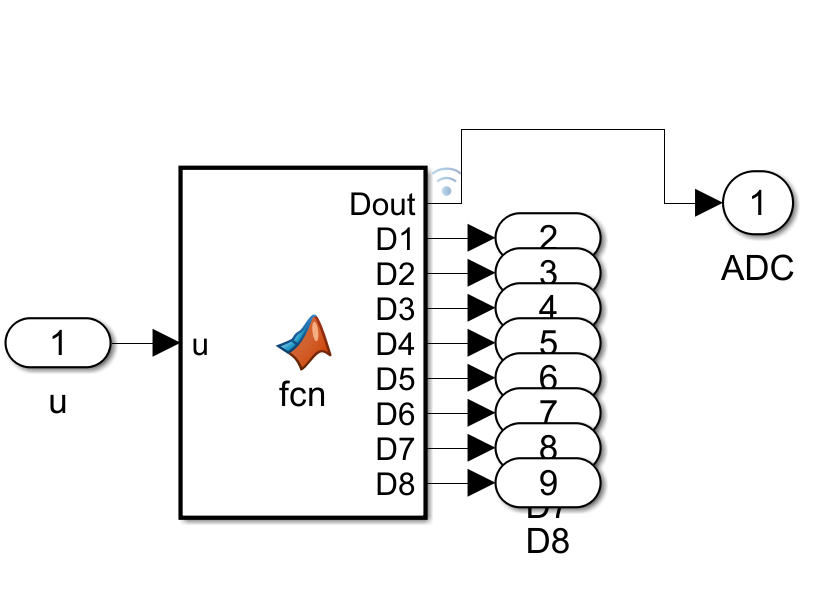
The diagram represents a Simulink model (possibly for digital signal processing or embedded systems simulation). Here’s a step-by-step explanation:
- Input ('u'): The model receives an input signal labeled as 'u' (with a value of 1 in this instance).
- MATLAB Function Block ('fcn'): The input 'u' is fed into a MATLAB Function block, which processes the input using a custom function ('fcn'). The function block outputs 8 digital signals labeled as `D1` to `D8` (collectively `Dout`).
- Digital Output Ports ('D1' to 'D8'): Each output from the function block is routed to a corresponding digital output port (numbered 2 to 9).
- ADC Block: The outputs from the digital ports are then combined and fed into an ADC (Analog-to-Digital Converter) block. The ADC output is labeled as '1'.
This model demonstrates the process of converting an analog signal into digital form using MATLAB/Simulink and visualizes the individual digital bits.
类别
在 帮助中心 和 File Exchange 中查找有关 Sources 的更多信息
2025-7-17
Community Treasure Hunt
Find the treasures in MATLAB Central and discover how the community can help you!
Start Hunting!
Translated by ![]()