SINR Map for a 5G Urban Macro-Cell Test Environment
This example shows how to construct a 5G urban macro-cell test environment and visualize the signal-to-interference-plus-noise ratio (SINR) on a map. The test environment is based on the guidelines defined in Report ITU-R M.[IMT-2020.EVAL] [1] for evaluating 5G radio technologies. This report defines several test environments and usage scenarios in Section 8.2. The test environment in this example is based on the urban environment with high user density and traffic loads focusing on pedestrian and vehicular users (Dense Urban-eMBB). The test environment includes a hexagonal cell network as well as a custom antenna array that is implemented using Phased Array System Toolbox™.
Define Network Layout
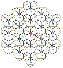
The test environment guidelines for 5G technologies reuse the test network layout for 4G technologies defined in Section 8.3 of Report ITU-R M.2135-1 [2], which is shown below. The layout consists of 19 sites placed in a hexagonal layout, each with 3 cells. The distance between adjacent sites is the inter-site distance (ISD) and depends on the test usage scenario. For the Dense Urban-eMBB test environment, the ISD is 200 m.

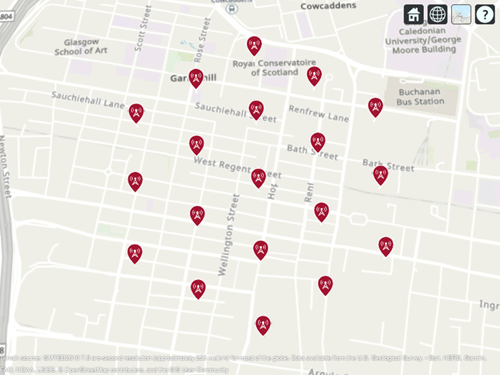
Create the locations corresponding to cell sites in the network layout, using MathWorks® Glasgow as the center location.
% Define center location site (cells 1-3)
centerSite = txsite(Name="MathWorks Glasgow",...
    Latitude=55.862787,...
    Longitude=-4.258523);

% Initialize arrays for distance and angle from center location to each cell site, where
% each site has 3 cells
numCellSites = 19;
siteDistances = zeros(1,numCellSites);
siteAngles = zeros(1,numCellSites);

% Define distance and angle for inner ring of 6 sites (cells 4-21)
isd = 200; % Inter-site distance
siteDistances(2:7) = isd;
siteAngles(2:7) = 30:60:360;

% Define distance and angle for middle ring of 6 sites (cells 22-39)
siteDistances(8:13) = 2*isd*cosd(30);
siteAngles(8:13) = 0:60:300;

% Define distance and angle for outer ring of 6 sites (cells 40-57)
siteDistances(14:19) = 2*isd;
siteAngles(14:19) = 30:60:360;
Define Cell Parameters
Each cell site has three transmitters corresponding to each cell. Create arrays to define the names, latitudes, longitudes, and antenna angles of each cell transmitter.
% Initialize arrays for cell transmitter parameters
numCells = numCellSites*3;
cellLats = zeros(1,numCells);
cellLons = zeros(1,numCells);
cellNames = strings(1,numCells);
cellAngles = zeros(1,numCells);

% Define cell sector angles
cellSectorAngles = [30 150 270];

% For each cell site location, populate data for each cell transmitter
cellInd = 1;
for siteInd = 1:numCellSites
    % Compute site location using distance and angle from center site
    [cellLat,cellLon] = location(centerSite, siteDistances(siteInd), siteAngles(siteInd));

    % Assign values for each cell
    for cellSectorAngle = cellSectorAngles
        cellNames(cellInd) = "Cell " + cellInd;
        cellLats(cellInd) = cellLat;
        cellLons(cellInd) = cellLon;
        cellAngles(cellInd) = cellSectorAngle;
        cellInd = cellInd + 1;
    end
end
Create Transmitter Sites
Create transmitter sites using parameters defined above as well as configuration parameters defined for Dense Urban-eMBB. Launch Site Viewer and set the map imagery using the Basemap property. Alternatively, open the basemap picker in Site Viewer by clicking the second button from the right. Select "Topographic" to choose a basemap with topography, streets, and labels.
% Define transmitter parameters using Table 8-2 (b) of Report ITU-R M.[IMT-2020.EVAL]
fq = 4e9; % Carrier frequency (4 GHz) for Dense Urban-eMBB
antHeight = 25; % m
txPowerDBm = 44; % Total transmit power in dBm
txPower = 10.^((txPowerDBm-30)/10); % Convert dBm to W

% Create cell transmitter sites
txs = txsite(Name=cellNames,...
    Latitude=cellLats,...
    Longitude=cellLons,...
    AntennaAngle=cellAngles,...
    AntennaHeight=antHeight,...
    TransmitterFrequency=fq,...
    TransmitterPower=txPower);

% Launch Site Viewer
viewer = siteviewer;

% Show sites on a map
show(txs);
viewer.Basemap = "topographic";

Create Antenna Element
Section 8.5 of ITU-R report [1] defines antenna characteristics for base station antennas. The antenna is modeled as having one or more antenna panels, where each panel has one or more antenna elements. Use Phased Array System Toolbox to implement the antenna element pattern defined in the report.
% Define pattern parameters
azvec = -180:180;
elvec = -90:90;
Am = 30; % Maximum attenuation (dB)
tilt = 0; % Tilt angle
az3dB = 65; % 3 dB bandwidth in azimuth
el3dB = 65; % 3 dB bandwidth in elevation

% Define antenna pattern
[az,el] = meshgrid(azvec,elvec);
azMagPattern = -12*(az/az3dB).^2;
elMagPattern = -12*((el-tilt)/el3dB).^2;
combinedMagPattern = azMagPattern + elMagPattern;
combinedMagPattern(combinedMagPattern<-Am) = -Am; % Saturate at max attenuation
phasepattern = zeros(size(combinedMagPattern));

% Create antenna element
antennaElement = phased.CustomAntennaElement(...
    AzimuthAngles=azvec,...
    ElevationAngles=elvec,...
    MagnitudePattern=combinedMagPattern,...
    PhasePattern=phasepattern);

% Display radiation pattern
f = figure;
pattern(antennaElement,fq);

Display SINR Map for Single Antenna Element
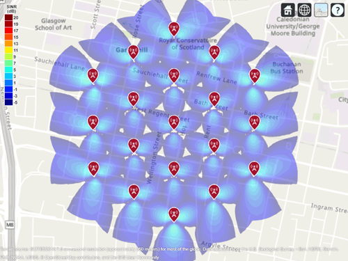
Visualize SINR for the test scenario using a single antenna element and the free space propagation model. For each location on the map within the range of the transmitter sites, the signal source is the cell with the greatest signal strength, and all other cells are sources of interference. Areas with no color within the network indicate areas where the SINR is below the default threshold of -5 dB.
% Assign the antenna element for each cell transmitter
for tx = txs
    tx.Antenna = antennaElement;
end

% Define receiver parameters using Table 8-2 (b) of Report ITU-R M.[IMT-2020.EVAL]
bw = 20e6; % 20 MHz bandwidth
rxNoiseFigure = 7; % dB
rxNoisePower = -174 + 10*log10(bw) + rxNoiseFigure;
rxGain = 0; % dBi
rxAntennaHeight = 1.5; % m

% Display SINR map
if isvalid(f)
    close(f)
end
sinr(txs,"freespace",...
    ReceiverGain=rxGain,...
    ReceiverAntennaHeight=rxAntennaHeight,...
    ReceiverNoisePower=rxNoisePower,...
    MaxRange=isd,...
    Resolution=isd/20)

Create 8-by-8 Rectangular Antenna Array
Define an antenna array to increase directional gain and increase peak SINR values. Use Phased Array System Toolbox to create an 8-by-8 uniform rectangular array.
% Define array size
nrow = 8;
ncol = 8;

% Define element spacing
lambda = physconst("lightspeed")/fq;
drow = lambda/2;
dcol = lambda/2;

% Define taper to reduce sidelobes
dBdown = 30;
taperz = chebwin(nrow,dBdown);
tapery = chebwin(ncol,dBdown);
tap = taperz*tapery.'; % Multiply vector tapers to get 8-by-8 taper values

% Create 8-by-8 antenna array
cellAntenna = phased.URA(Size=[nrow ncol],...
    Element=antennaElement,...
    ElementSpacing=[drow dcol],...
    Taper=tap,...
    ArrayNormal="x");

% Display radiation pattern
f = figure;
pattern(cellAntenna,fq);

Display SINR Map for 8-by-8 Antenna Array
Visualize SINR for the test scenario using a uniform rectangular antenna array and the free space propagation model. Apply a mechanical downtilt to illuminate the intended ground area around each transmitter.
% Assign the antenna array for each cell transmitter, and apply downtilt.
% Without downtilt, pattern is too narrow for transmitter vicinity.
downtilt = 15;
for tx = txs
    tx.Antenna = cellAntenna;
    tx.AntennaAngle = [tx.AntennaAngle; -downtilt];
end

% Display SINR map
if isvalid(f)
    close(f)
end
sinr(txs,"freespace",...
    ReceiverGain=rxGain,...
    ReceiverAntennaHeight=rxAntennaHeight,...
    ReceiverNoisePower=rxNoisePower,...
    MaxRange=isd,...
    Resolution=isd/20)

Display SINR Map Using Close-In Propagation Model
Visualize SINR for the test scenario using the Close-In propagation model [3], which models path loss for 5G urban micro-cell and macro-cell scenarios. This model produces an SINR map that shows reduced interference effects compared to the free space propagation model.
sinr(txs,"close-in",...
    ReceiverGain=rxGain,...
    ReceiverAntennaHeight=rxAntennaHeight,...
    ReceiverNoisePower=rxNoisePower,...
    MaxRange=isd,...
    Resolution=isd/20)

Use Rectangular Patch Antenna as Array Element
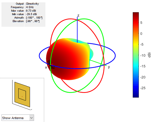
The analysis above used an antenna element that was defined using the equations specified in the ITU-R report [1]. The antenna element needs to provide a maximum gain of 9.5 dBi and a front-to-back ratio of approximately 30 dB. Now replace the equation-based antenna element definition with a real antenna model using a standard half-wavelength rectangular microstrip patch antenna. The antenna element provides a gain of about 9 dBi, although with a lower front-to-back ratio.
% Design half-wavelength rectangular microstrip patch antenna
patchElement = design(patchMicrostrip,fq);
patchElement.Width = patchElement.Length;
patchElement.Tilt = 90;
patchElement.TiltAxis = [0 1 0];

% Display radiation pattern
f = figure;
pattern(patchElement,fq)

Warning: An error occurred while drawing the scene: GraphicsView error in command: interactionsmanagermessage:  TypeError: Cannot read properties of null (reading '_gview')
    at new g (https://127.0.0.1:31515/toolbox/matlab/uitools/figurelibjs/release/bundle.mwBundle.gbtfigure-lib.js?mre=https
Display SINR Map Using the Patch Antenna Element in the 8-by-8 Array
Update the SINR map for the Close-In propagation model [3] using the patch antenna as the array element. This analysis should capture the effect of deviations from an equation-based antenna specification as per the ITU-R report [1], including:
Variations in peak gain
Variations in pattern symmetry with spatial angles
Variations in front-to-back ratios
% Assign the patch antenna as the array element
cellAntenna.Element = patchElement;

% Display SINR map
if isvalid(f)
    close(f)
end
sinr(txs,"close-in",...
    ReceiverGain=rxGain,...
    ReceiverAntennaHeight=rxAntennaHeight,...
    ReceiverNoisePower=rxNoisePower,...
    MaxRange=isd,...
    Resolution=isd/20)

Summary
This example shows how to construct a 5G urban macro-cell test environment consisting of a hexagonal network of 19 cell sites, each containing 3 sectored cells. The signal-to-interference-plus-noise ratio (SINR) is visualized on a map for different antennas. The following observations are made:
A rectangular antenna array can provide greater directionality and therefore peak SINR values than use of a single antenna element.
The outward-facing lobes on the perimeter of the SINR map represent areas where less interference occurs. A more realistic modeling technique would be to replicate, or wrap around, cell sites to expand the geometry so that perimeter areas experience similar interference as interior areas.
Using a rectangular antenna array, a propagation model that estimates increased path loss also results in higher SINR values due to less interference.
Two antenna elements are tried in the antenna array: an equation-based element using Phased Array System Toolbox and a patch antenna element using Antenna Toolbox™. These produce similar SINR maps.
References
[1] Report ITU-R M.[IMT-2020.EVAL], "Guidelines for evaluation of radio interface technologies for IMT-2020", 2017. https://www.itu.int/md/R15-SG05-C-0057
[2] Report ITU-R M.2135-1, "Guidelines for evaluation of radio interface technologies for IMT-Advanced", 2009. https://www.itu.int/dms_pub/itu-r/opb/rep/R-REP-M.2135-1-2009-PDF-E.pdf
[3] Sun, S.,Rapport, T.S., Thomas, T., Ghosh, A., Nguyen, H., Kovacs, I., Rodriguez, I., Koymen, O.,and Prartyka, A. "Investigation of prediction accuracy, sensitivity, and parameter stability of large-scale propagation path loss models for 5G wireless communications." IEEE Transactions on Vehicular Technology, Vol 65, No.5, pp.2843-2860, May 2016.
See Also
Functions
Objects
txsite|siteviewer|phased.CustomAntennaElement(Phased Array System Toolbox) |phased.URA(Phased Array System Toolbox)