Measure and Manage Impulse Responses
In this tutorial, explore key functionality of the Impulse Response Measurer. The Impulse Response Measurer app enables you to
Configure your audio I/O system.
Acquire impulse response (IR) measurements using either the exponential swept sine (ESS) or maximum length sequences (MLS) methods.
View and manage captured IR data.
Export the data to a file, workspace, or other app for further study.
Generate a script that performs IR measurements according to the current settings.
To begin, open the Impulse Response Measurer app by selecting the ![]() icon from the app gallery.
icon from the app gallery.
Configure Audio I/O System
The Impulse Response Measurer app enables you to specify an audio device, sample rate, samples per frame, player channel, and recorder channel. The audio device must be a real or virtual device enabled for simultaneous playback and recording (full-duplex mode) and must use a supported driver. Supported drivers are platform-specific:
Windows® –– ASIO™: Click the
 button to open the settings panel for the
ASIO driver.
button to open the settings panel for the
ASIO driver.Mac –– CoreAudio
Linux® –– ALSA
Valid values for sample rate and number of samples per frame depend on your specified audio device.
You can use the level monitor to verify the configuration of your audio I/O system.
Loopback Cable for Latency Measurement
To measure the audio device latency and remove it from captured measurements, you must use a loopback cable to connect one of the device player channels directly to one of the recorder channels.

To enable latency measurement and removal, click the Latency
Compensation drop-down list, select Loopback
Measurement, and then set the Loopback
Channels to the player and recorder channels that are connected
by the loopback cable.
This example sets Latency Compensation to
None, so it does not measure the audio device
latency.
Configure IR Acquisition Method
To configure your IR acquisition method, use the Method and Method Settings sections of the toolstrip.

You can select the method to acquire IR measurements as either:
Maximum Length Sequences(MLS)Exponential Swept Sine(Swept Sine)
Both methods for IR acquisition have the same basic settings, including:
Number of Runs –– Number of times the excitation signal is sent within a single capture. Multiple runs are used to average individual impulse response captures to reduce measurement noise.
Duration per Run (s) –– Total time of each run in seconds.
Excitation Level (dBFS) –– The level of the excitation signal in dBFS.
Both methods for IR acquisition also have the same advanced run settings, including:
Wait before first run –– Delay before starting the first run. The delay allows time for any last-minute tasks, such as exiting a room before testing its acoustics.
Pause between runs –– Duration of the pause between runs. During a pause, the excitation signal is not sent, and audio is not recorded. When using the Swept Sine method, include a pause between runs to avoid buildup of reverberations. Pause between runs is always zero for the MLS method.
Number of warmup runs –– Number of times to output the excitation signal before acquisition. The MLS method assumes the signal it acquires is a combination of the excitation signal and its impulse response.
The total capture time is a sum of run durations, pauses, and the initial wait.

The Swept Sine method has additional Advanced Settings to control the excitation signal, including:
Sweep start frequency
Sweep stop frequency
Sweep duration
End silence duration
When using the Swept Sine method, the Run Duration is divided into Sweep duration and End silence duration. During the end silence, the app continues to record audio, enabling acquisition of the response over the entire range of the frequency sweep.
Starting in R2022a, you can automatically save device, method, and advanced settings and use them in future measurement sessions.
Acquire IR Measurements
For this example, use the Swept Sine method with default settings. Once you have your audio device set up, click Capture. A dialog box opens that displays the progress of your capture. Capture IR measurements twice.

Analyze and Manage IR Measurements
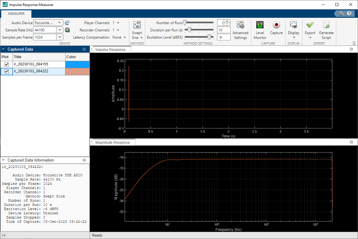
After the capture, the Impulse Response Measurer app stores the
captured data locally. The Captured Data panel displays the
title of the captured data, the colors used for plotting, and information about the
settings used to acquire the data. You can double-click the color to choose which
color you want associated with each impulse response. You can also double-click the
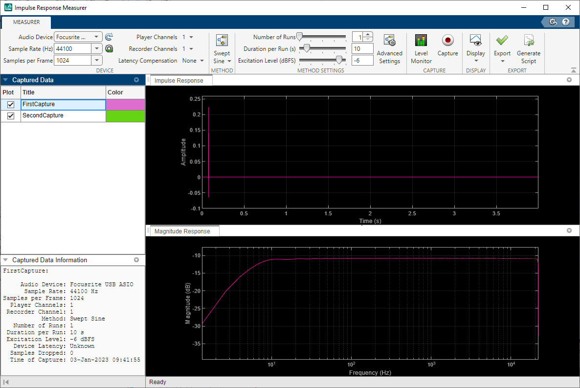
title to rename your captured data. Rename your captures as
FirstCapture and SecondCapture, and change
the colors to pink and green. To make one impulse response plot appear on top of the
other, select the title under Captured Data. Select the capture
you relabeled FirstCapture.

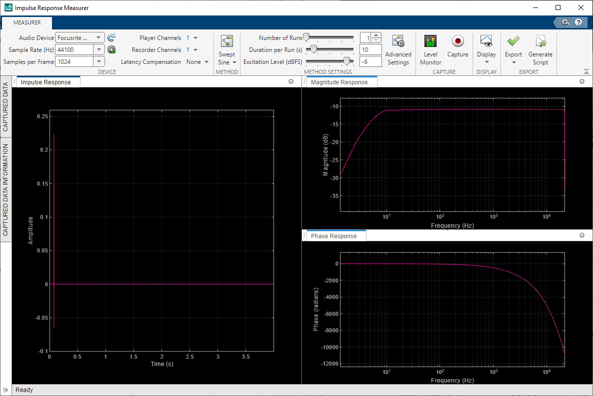
By default, the impulse response and magnitude response are plotted. You can view any combination of the impulse, magnitude, and phase response using the Display button. Here you can also remove the measured audio device latency from the plotted impulse response and phase response.

Minimize Captured Data and Captured Data Information, then select the Phase Response.

You can toggle the relative size of the plot by moving the dividers. You can zoom
in and out or toggle between linear and logarithmic frequency axes by selecting the
icons that appear when your pointer is over the plot. Updating either the magnitude
response or the phase response updates the other. Zoom in on the impulse response
plot and in the range 0–20 Hz of your frequency response plots. Zooming in, you can
see the small delay between FirstCapture and
SecondCapture. When the zoom level is high enough, line
markers automatically appear.

Export IR Measurements
To view export options for further analysis or use, click Export.

Export the data to your workspace. The data is saved as a table. To inspect how the data is saved, display the table you exported.
irdata_160957
irdata_160957 =

  2×17 table

                             TimeOfCapture             ImpulseResponse           Device           SampleRate    SamplesPerFrame    PlayerChannels    RecorderChannel       Method       NumRuns    DurationPerRun    ExcitationLevel    RawAudioData    SamplesDropped    DeviceLatencyInSamples    OtherMetaData    MagnitudeResponse    PhaseResponse
                     ______________________________    _______________    ____________________    __________    _______________    ______________    _______________    ____________    _______    ______________    _______________    ____________    ______________    ______________________    _____________    _________________    _____________

    FirstCapture     30-Jun-2022 15:59:42 UTC-04:00      1×1 struct       "Focusrite USB ASIO"      44100            1024              {[1]}                1           "Swept Sine"       1             4                 -6            1×1 struct           0                    NaN               1×1 struct         1×1 struct         1×1 struct
    SecondCapture    30-Jun-2022 15:59:54 UTC-04:00      1×1 struct       "Focusrite USB ASIO"      44100            1024              {[1]}                1           "Swept Sine"       1             4                 -6            1×1 struct           0                    NaN               1×1 struct         1×1 struct         1×1 struct
When you export the data as a MAT-file, the same table is saved as when you export
to the workspace. When you select to export the data as a WAV file, each impulse
response is saved as a separate WAV file. The title of the capture is the name of
the WAV file. In this example, selecting to export data to audio WAV file places two
WAV files in the specified folder, FirstCapture.wav and
SecondCapture.wav.
To analyze your captured data further, view the data in Signal Analyzer.
Generate MATLAB Code
You can generate MATLAB® code that measures impulse responses using the current settings of the app. To open an untitled script in the MATLAB editor containing the code, click Generate Script in the Export section of the toolstrip.

Run the script to measure the impulse response and store the captured data in the
capture structure.
capture
capture =

  struct with fields:

      ImpulseResponse: [1×1 struct]
    MagnitudeResponse: [1×1 struct]
        PhaseResponse: [1×1 struct]
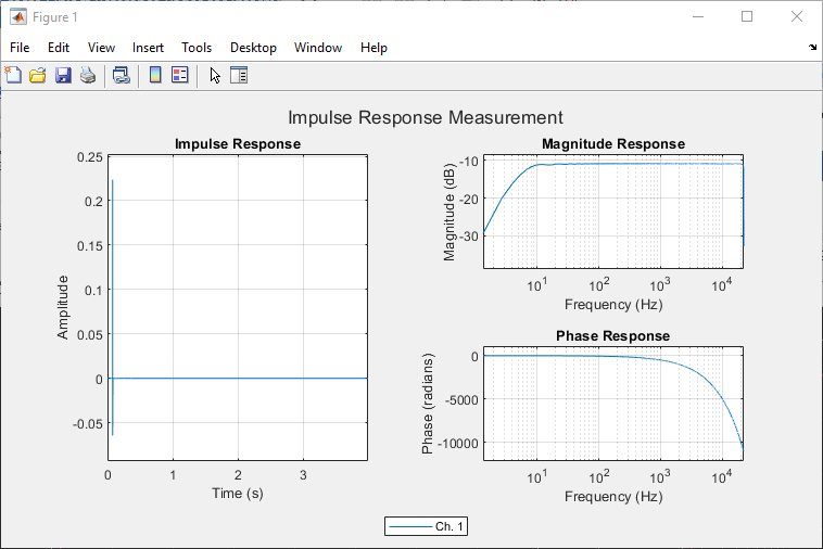
The script optionally plots the impulse, magnitude, and phase response according to the Display settings in the app.

You can examine the generated code to understand how the app performs the measurement, and you can edit the script for customization.
See Also
Impulse Response
Measurer | audioPlayerRecorder | splMeter | reverberator