Main Content

Gearbox

Ideal rotational gearbox

  • Gearbox block

Libraries:
Powertrain Blockset / Drivetrain / Couplings

Description

The Gearbox block implements an ideal rotational gearbox. The block uses the gear inertias and damping to calculate the velocity response to the base and follower gear pair input torques.

In fuel economy and powertrain efficiency studies, you can use the Gearbox block to model ideal gear coupling and the power transfer between common driveline elements such as transmissions, engines, clutches, and differentials.

The Gearbox block uses these equations to approximate the transmission dynamics.

ω˙BJB=ωBbB+ηNTFω˙FJF=ωFbF+ηTF

This constraint equation reduces the system to a one DOF system.

ωB=NωF

To express the ideal torque transfer, the block uses this relationship.

ηNTB+TF=0

Efficiency

To account for the block efficiency, use the Efficiency factors parameter. This table summarizes the block implementation for each setting.

SettingImplementation

Constant

Constant efficiency that you can set with the Constant efficiency factor, eta parameter.

Driveshaft torque, temperature and speed

Efficiency as a function of base gear input torque, air temperature, and driveshaft speed. Use these parameters to specify the lookup table and breakpoints:

  • Efficiency lookup table, eta_tbl

  • Efficiency torque breakpoints, Trq_bpts

  • Efficiency speed breakpoints, omega_bpts

  • Efficiency temperature breakpoints, Temp_bpts

For the air temperature, you can either:

  • Select Input ambient temperature to create an input port.

  • Set a Ambient temperature, Tamb parameter value.

To select the interpolation method, use the Interpolation method parameter. For more information, see Interpolation Methods.

Power Accounting

For the power accounting, the block implements these equations.

Bus Signal DescriptionVariableEquations

PwrInfo

PwrTrnsfrd — Power transferred between blocks

  • Positive signals indicate flow into block

  • Negative signals indicate flow out of block

PwrBase

Mechanical power from base shaft

PBase

PBase= ηTBωB

PwrFlwr

Mechanical power from follower shaft

PFlwr

PFlwr= ηTFωF

PwrNotTrnsfrd — Power crossing the block boundary, but not transferred

  • Positive signals indicate an input

  • Negative signals indicate a loss

PwrMechLoss

Total power loss

Png

Png= (Pt+Pd)+PsPt=ηTBωB+ηTFωF

PwrDampLoss

Power loss due to damping

Pd

Pd=(bF|ωF|2+bB|ωB|2)

PwrStored — Stored energy rate of change

  • Positive signals indicate an increase

  • Negative signals indicate a decrease

PwrStoredShft

Rate change of stored internal kinetic energy

Ps

Ps=(ωBω˙BJB+ωFω˙FJF)

The equations use these variables.

TB

Base gear input torque

TF

Follower gear output torque

ωB

Base gear angular velocity

ωF

Follower gear angular velocity

JB

Base gear rotational inertia

JF

Follower gear rotational inertia

bB

Base gear rotational viscous damping

bF

Follower gear rotational viscous damping

N

Torque transmission gear ratio

η

Gear efficiency

Pt

Total power

Pd

Power loss due to damping

Ps

Rate change of stored internal kinetic energy

Examples

Ports

Input

expand all

Base gear input torque, TB, in N·m.

Dependencies

To create this port, for Port Configuration, select Simulink.

Follower gear output torque, TF, in N·m.

Dependencies

To create this port, for Port Configuration, select Simulink.

Base gear angular velocity, ωB, in rad/s. Base gear torque, TB, in N·m.

Dependencies

To create this port, for Port Configuration, select Two-way connection.

Ambient air temperature, Tair, in K.

Dependencies

To enable this port:

  • Set Efficiency factors to Driveshaft torque, speed and temperature.

  • Select Input ambient temperature.

Output

expand all

Bus signal containing these block calculations.

SignalDescriptionVariableUnits
Base

BaseTrq

Base gear input torque

TBN·m

BaseSpd

Base gear angular velocity

ωBrad/s
Flwr

FlwrTrq

Follower gear torque

TFN·m

FlwrSpd

Follower gear angular velocity

ωFrad/s
PwrInfo

PwrTrnsfrd

PwrBase

Mechanical power from base shaft

PBase

W
PwrFlwr

Mechanical power from follower shaft

PFlwr

W

PwrNotTrnsfrd

PwrMechLoss

Total gear power loss

Png

W
PwrDampLoss

Power loss due to damping

Pd

W

PwrStored

PwrStoredShft

Rate change of stored internal kinetic energy

Ps

W

Base gear angular velocity, ωB, in rad/s.

Dependencies

To create this port, for Port Configuration, select Simulink.

Follower gear angular velocity, ωF, in rad/s.

Dependencies

To create this port, for Port Configuration, select Simulink.

Follower gear angular velocity, ωF, in rad/s. Follower gear torque, TF, in N·m.

Dependencies

To create this port, for Port Configuration, select Two-way connection.

Parameters

expand all

Block Options

Specify the port configuration.

Dependencies

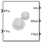
Specifying Simulink creates these ports:

  • BSpd

  • FSpd

  • BTrq

  • FTrq

Specifying Two-way connection creates these ports:

  • B

  • F

To account for the block efficiency, use the Efficiency factors parameter. This table summarizes the block implementation for each setting.

SettingImplementation

Constant

Constant efficiency that you can set with the Constant efficiency factor, eta parameter.

Driveshaft torque, temperature and speed

Efficiency as a function of base gear input torque, air temperature, and driveshaft speed. Use these parameters to specify the lookup table and breakpoints:

  • Efficiency lookup table, eta_tbl

  • Efficiency torque breakpoints, Trq_bpts

  • Efficiency speed breakpoints, omega_bpts

  • Efficiency temperature breakpoints, Temp_bpts

For the air temperature, you can either:

  • Select Input ambient temperature to create an input port.

  • Set a Ambient temperature, Tamb parameter value.

To select the interpolation method, use the Interpolation method parameter. For more information, see Interpolation Methods.

For more information, see Interpolation Methods.

Dependencies

To enable this parameter, set Efficiency factors to Driveshaft torque, speed and temperature.

Select to specify that the output shaft rotates in the same direction as the input.

Select to create input port AirTemp for the ambient air temperature.

Dependencies

To enable this parameter, set Efficiency factors to Driveshaft torque, speed and temperature.

Base-to-follower gear ratio, dimensionless.

Base shaft inertia, in kg·m^2.

Follower shaft inertia, in kg·m^2.

Base viscous shaft damping, in N·m· s/rad.

Follower viscous shaft damping, in N·m· s/rad.

Base shaft initial velocity, in rad/s.

Efficiency

Constant efficiency, η.

Dependencies

To enable this parameter, set Efficiency factors to Constant.

Dimensionless array of values for efficiency as a function of:

  • M input torques

  • N input speed

  • L air temperatures

Each value specifies the efficiency for a specific combination of torque, speed, and temperature. The array size must match the dimensions defined by the torque, speed, and temperature breakpoint vectors.

Dependencies

To enable this parameter, set Efficiency factors to Driveshaft torque, speed and temperature.

Vector of input torque, breakpoints for efficiency, in N·m.

Dependencies

To enable this parameter, set Efficiency factors to Driveshaft torque, speed and temperature.

Vector of speed, breakpoints for efficiency, in rad/s.

Dependencies

To enable this parameter, set Efficiency factors to Driveshaft torque, speed and temperature.

Vector of ambient temperature breakpoints for efficiency, in K.

Dependencies

To enable this parameter, set Efficiency factors to Driveshaft torque, speed and temperature.

Ambient air temperature, Tair, in K.

Dependencies

To enable this parameter:

  • Set Efficiency factors to Driveshaft torque, speed and temperature.

  • Clear Input ambient temperature.

Extended Capabilities

C/C++ Code Generation
Generate C and C++ code using Simulink® Coder™.

Version History

Introduced in R2017a