OFDM 简介
正交频分复用 (OFDM) 通过将调制的高带宽信号载波划分到许多调制的窄带子载波上来实现高速率数据传输。对于 OFDM 传输,使用窄带子载波可降低对频率选择性衰落的敏感性。许多最新的无线标准和电信标准都使用多载波 OFDM 调制格式。在单载波系统中,支持高数据速率需要宽带宽载波,因此符号持续时间短。通过频率选择性多径信道对宽带宽载波进行滤波会严重降低信号质量,因为信道冲激响应在时间上跨多个符号,并使信号易受符号间干扰 (ISI) 的影响。
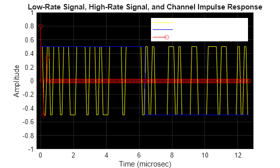
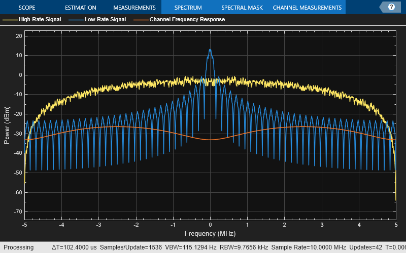
这些时域图和频域图显示低速率信号、高速率信号和频率选择性多径信道响应。时域图显示信道冲激响应很容易包含在低速率信号的符号中,但它跨高速率信号的多个符号。频域图显示信道幅值在低速率信号的通带上非常平坦,但在高速率信号的通带上变化很大,从而导致 ISI。
sa = helperPlotMultipath;
为了在发射许多并行低带宽信号时避免 ISI,各个子载波必须相互正交。通过发射许多正交的低带宽子载波来避免 ISI 催生了 OFDM 这种技术。OFDM 调制器可将高速率串行符号流转换为许多并行低速率流。每个正交低速率流遇到的信道相对平坦,ISI 最小,且易于均衡。
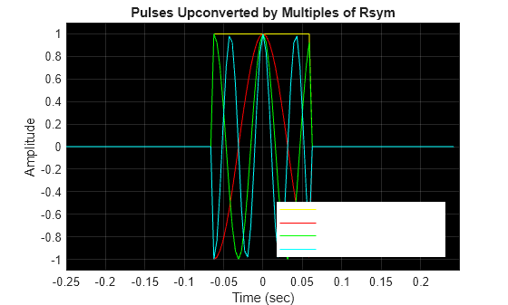
为了演示,我们假设有一个持续时间为 、符号数据速率为 的脉冲,以及在频率上平移了 、2 和 3 的其他脉冲。在频率上平移的脉冲称为子载波。这些图显示时域和频域中的子载波。
helperPlotOFDM
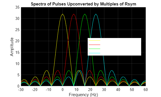
频域图显示正交的频率平移脉冲,每个子载波的频谱峰值出现在所有其他脉冲的过零点。
OFDM 调制器对所有这些子载波求和以形成其输出信号。此处,使用 QAM 方法对子载波进行了基带调制。从数学上讲,采样的调制器输出信号 由下式给出:
其中
是第 个子载波在第 个 OFDM 时间符号中的 QAM 调制符号
是每个低速率 QAM 流的符号速率
是子载波数量或低速率 QAM 流数量
此方程简化为
它是 QAM 符号流 的离散傅里叶逆变换 (IDFT) 的缩放版本。
另请参阅
函数
fft|ifft|ofdmmod|ofdmdemod|nrOFDMModulate(5G Toolbox) |nrOFDMDemodulate(5G Toolbox) |lteOFDMModulate(LTE Toolbox) |lteOFDMDemodulate(LTE Toolbox) |wlanWaveformGenerator(WLAN Toolbox)