使用基于 FFT 过采样的 OFDM
以下示例修改了 OFDM+CP 信号,以从 OFDM 调制器高效输出过采样波形。简单的场景配置:将采样率与子载波间隔和 FFT 长度相关联。
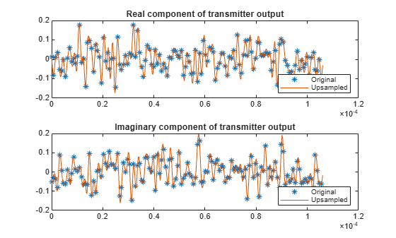
k = 4;       % Number of bits per symbol
M = 2^k;     % Modulation order
nFFT = 128;  % Number of FFT bins
cplen = 8;   % CP length
txsymbols = randi([0 M-1],nFFT,1);
txgrid = qammod(txsymbols,M,UnitAveragePower=true);
txout = ifft(txgrid,nFFT);
txout = txout(:); % Vectorize matrix if processing multiple symbols
txcp = txout(nFFT-cplen+1:nFFT);
txout = [txcp; txout];

scs = 20e3;        % Subcarrier spacing in Hz
Fs = scs * nFFT/2; % Sampling rate (1.28e6 Hz)
Ts = 1 / Fs;       % Sample duration in seconds

Tend = Ts * (length(txout)-1);
subplot(211)
hold off
plot(0:Ts:Tend,real(txout),"*")
title("Real component of transmitter output")
subplot(212)
hold off
plot(0:Ts:Tend,imag(txout),"*")
title("Imaginary component of transmitter output")
定义大于 nFFT 的 FFT 长度,以在时域中实现过采样。为便于后续比较,在 txgrid 的中间插入零,以保持原始信号和上采样信号的 bin 中心之间的对应关系。这里提供了一个控制选项,使您能够调整 OFDM 调制器输出和解调器输入使用的整数过采样率。
upFactor =3; nFFTUp = upFactor * nFFT; fftgrid = [txgrid(1:nFFT/2); ... zeros((upFactor-1)*nFFT,1); ... txgrid((nFFT/2+1):nFFT)]; % Each column of fftgrid is one OFDM symbol txout = upFactor * ifft(fftgrid,nFFTUp); % Vectorize the matrix to process multiple OFDM symbols txout = txout(:); cplenUp = cplen * upFactor; txcp = txout(nFFTUp-cplenUp+1:nFFTUp); txout = [txcp; txout]; Ts = 1 / (upFactor*Fs); Tend = Ts * (length(txout)-1); subplot(211) hold on plot(0:Ts:Tend,real(txout)) legend ("Original","Upsampled","Location","southeast") subplot(212) hold on plot(0:Ts:Tend,imag(txout)) legend ("Original","Upsampled","Location","southeast")
通过向接收的信号添加噪声、频率依赖性和延迟的信道对发射进行滤波。
hchan = [0.4 1 0.4].';
rxin = awgn(txout,40);       % Add noise
rxin = conv(rxin,hchan);     % Add frequency dependency
channelDelay = dsp.Delay(1); % Could use fractional delay
rxin = channelDelay(rxin);   % Add delay
添加一个小于 CP 长度的随机偏移量。偏移量设置为零表示发射信号和接收信号之间完美同步。任何小于 CP 长度的定时偏移量都可以通过附加线性相位的均衡来补偿。为了在 FFT 处理之前直接比较不同速率的信号,可通过上采样因子对同步信号进行归一化。
offset = (randi(cplenUp) - 1); % random offset less than length of CP
% Remove CP and synchronize the received signal
rxsync = rxin(cplenUp+1+channelDelay.Length-offset:end);

rxgrid = fft(rxsync(1:nFFTUp),nFFTUp)/upFactor;
实际系统在信号恢复过程中需要进行信道估计。OFDM 和 CP 的组合将均衡简化为每个频率 bin 对应一个复数标量。只要延迟不超过 CP 长度,信道估计器就可以完成同步。这里提供了一个控制选项,使您能够通过在接收机前端禁用均衡来进行试验。
useEqualizer =true; if useEqualizer hfchan = fft(hchan,nFFTUp); % Linear phase term related to timing offset offsetf = exp(-1i * 2*pi*offset * (0:nFFTUp-1).'/nFFTUp); rxgrideq = rxgrid ./ (hfchan .* offsetf); else % Without equalization errors occur rxgrideq = rxgrid; end rxgridNoZeroPad = [rxgrideq(1:nFFT/2); ... rxgrideq((1+(upFactor-0.5)*nFFT):end)]; rxsymbols = qamdemod(rxgridNoZeroPad,M,UnitAveragePower=true); if max(txsymbols - rxsymbols) < 1e-8 disp("Oversampled receiver output matches transmitter input."); else disp("Received symbols do not match transmitted symbols.") end
Oversampled receiver output matches transmitter input.