ofdmPilotConfig
R2026bDescription
The ofdmPilotConfig object specifies the pilot location and pilot
symbol configuration for OFDM systems. Use this object to construct pilot symbol patterns
for user-defined OFDM systems and provide pilot symbol information to the
ofdmChannelEstimate function.
Creation
Syntax
Description
creates an OFDM
pilot configuration object that specifies the pilot locations and the pilot symbol
configuration for a MIMO-OFDM system.pilotcfg = ofdmPilotConfig
sets one or more properties using name-value arguments. For example,
pilotcfg = ofdmPilotConfig(PropertyName=Value)FFTLength=64 sets the total number of subcarriers to
64.
configures the output object by setting the:pilotcfg = ofdmPilotConfig(fftlen,numGuardBandCarriers,numSym,numTxStreams)
FFTLengthproperty to thefftleninput value.NumGuardBandCarriersproperty to thenumGuardBandCarriersinput value.NumSymbolsproperty to thenumSyminput value.NumTransmitStreamsproperty to thenumTxStreamsinput value.
The object computes values for the StreamGroups, PilotLocations, and PilotSymbols properties based on input argument values. For this
syntax, the number of transmit streams must be a nonnegative integer power of 2. For
more information, see Computing Pilot Cluster Locations from FFT Length and Transmit Streams and Choosing Pilot Symbols for Pilot Locations.
Properties
FFT length for OFDM symbols, specified as a positive integer scalar.
Data Types: double
Number of subcarriers allocated to the left and right guard bands, specified as
2-by-1 integer vector, [NleftG;
NrightG]. Total number of subcarriers
in the guard bands, sum(NumGuardBandCarriers) <
FFTLength.
Data Types: double
Number of OFDM symbols in the OFDM grid, specified as a positive integer scalar.
Data Types: double
Number of transmit streams, specified as a positive integer scalar.
Data Types: double
Grouping of transmit streams, specified as a nonempty cell array of vectors.
Vectors in the cell array indicate streams that transmit at the same OFDM
subcarriers and using the same OFDM symbols. The property must assign each
transmit stream [1:NumTransmitStreams] in exactly one of the vector groups. Each
transmit stream must appear in exactly one group and you must include all streams
as specified by the NumTransmitStreams property.
Example: For NumTransmitStreams = 3, setting
StreamGroups = {[1 2], [3]} divides the three transmit
streams into two groups. Streams 1 and 2 transmit on the same subcarriers and use
the same symbols and must be orthogonal to avoid interference with each other.
Stream 3 transmits in a separate group.
Data Types: double
Pilot locations for each pilot cluster in each stream group, specified as a
nonempty cell array in which each cell contains a 3D array defining pilot clusters
for one stream group. To specify pilot locations based on rectangular patterns,
use the ofdmPilotGrid function.
The number of elements in
PilotLocationsmust be equal to the number of elements inStreamGroups.For each stream group, g,
PilotLocations{g}is an M(g)-by-2-by-N(g) array where:M(g) is the number of pilot symbols per cluster for stream group g. This value must be greater than or equal to the number of streams groups.
The columns dimension configures 2 columns. The first column,
PilotLocations{g}(:,1,:), specifies the subcarrier indices of all the pilots and the second column,PilotLocations{g}(:,2,:), specifies OFDM symbol indices of all the pilots.N(g) is the number of clusters for group g.
Subcarrier indices are integers in the range [
(NumGuardBandCarriers(1) + 1),(FFTLength – NumGuardBandCarrier(2))].Symbol indices are integers in the range [1,
NumSymbols].
Example: The default setting for PilotLocations places
pilot symbols in two OFDM symbols and spreads them evenly across subcarriers.
7:4:59 repeated defines two sets of pilot symbol subcarrier
indices to 7,11,15,…,59, spaced by 4 subcarriers.
ones(1,14) are the pilot symbol indices for the first set.
All these pilot symbols are in the first OFDM symbol.
14*ones(1,14) are the symbol indices for the second set. All
these pilots symbols are in the fourteenth OFDM symbol.
reshape(...,1,2,28) organizes the values into a 3D array of
one cluster group, two columns (subcarrier index and symbol index), and 28 pilot
positions.
Data Types: cell
Pilot symbol values for each stream group, specified as a nonempty cell array of 3D array of complex numbers.
The number of elements in the pilot symbols must be equal to the number of elements in the stream groups.
In the 3D array:
size(PilotLocations{g},1) — The first dimension is the number of pilot symbols per cluster. This value must match the number of pilot positions inPilotLocations{g}.size(PilotSymbols{g},2) — The second dimension is the number of streams in the group. Each pilot position has only one value for each stream.size(PilotSymbols{g},3) — The third dimension is the number of clusters. This value must match the number of clusters inPilotLocations{g}.
For each cluster n, the matrix of pilot symbols (
PilotSymbols{g}(:,:,n)) must have full rank. Full rank means that pilots for all streams in that cluster must be orthogonal, so the receiver can separate them when estimating the channel.PilotSymbols{g}(m,:,n)—These values are the pilot symbol values for the mth pilot position in the nth cluster for all streams in the group g.
For more information, see Choosing Pilot Symbols for Pilot Locations.
Example: The default setting for PilotSymbols assigns one
stream group with 28 clusters and one pilot symbol per cluster.
comm.PNSequence(SamplesPerFrame=56).step() defines a 56 bit
PN sequence. pskmod(...,4,pi/4,'InputType','bit'), QPSK
modulates the bits to values for 28 pilot symbols.
reshape(...,1,1,28) organizes the modulated sequence into a
3D array of one pilot cluster position, one stream group, and 28 pilot positions
to match the structure of PilotLocations.
Data Types: double
Complex Number Support: Yes
Output Arguments
Pilot configuration object for an OFDM system, returned as an
ofdmPilotConfig object.
Object Functions
validate | Validate contents of ofdmPilotConfig object |
pilotSignal | Returns pilot symbols and linear indices of pilot locations |
plot | Plot pilot locations in 3-D |
Examples
Plot the default OFDM pilots for the ofdmPilotConfig configuration object.
Specify an OFDM pilot configuration using default values.
pilotcfg = ofdmPilotConfig
pilotcfg =
ofdmPilotConfig with properties:
FFTLength: 64
NumGuardBandCarriers: [2×1 double]
NumSymbols: 14
NumTransmitStreams: 1
StreamGroups: {[1]}
PilotLocations: {[1×2×28 double]}
PilotSymbols: {[1×1×28 double]}
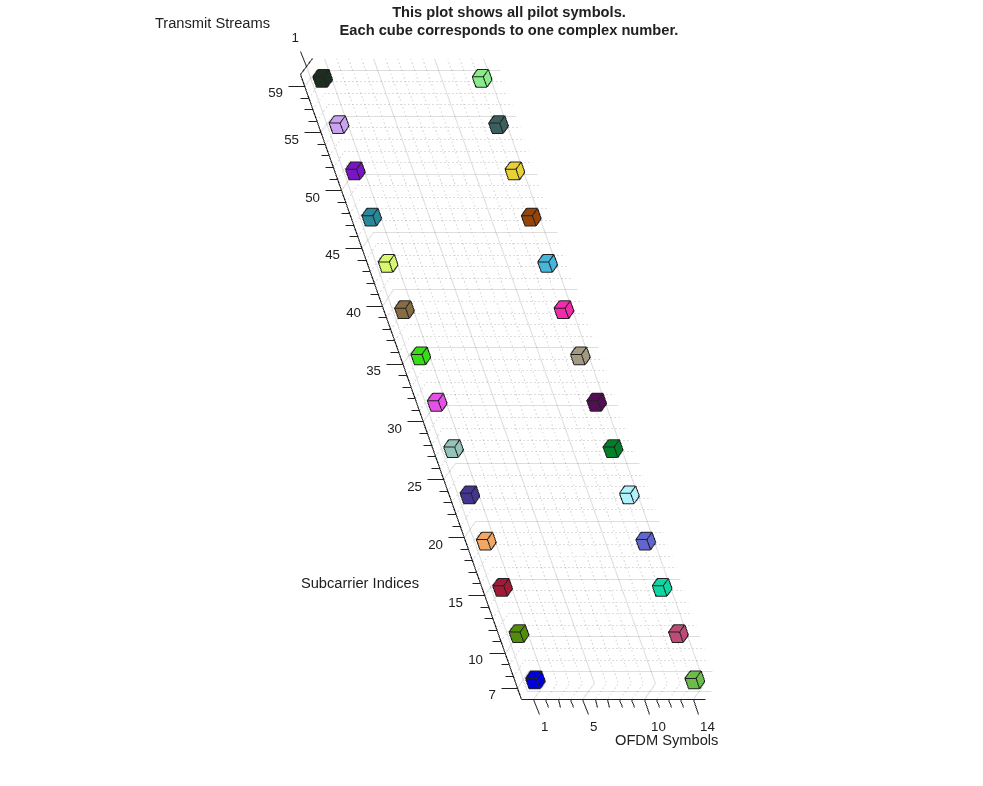
Plot the pilot configuration. The tilted 3D-style plot shows all pilot symbols in an OFDM system. Colored cubes represent individual complex pilot symbols, arranged diagonally by transmit stream. The horizontal axis is OFDM Symbols (indices 1–14), the vertical axis is Subcarrier Indices (7–59). Each cube marks a pilot location across subcarriers and OFDM symbols.
plot(pilotcfg)
Create an OFDM system with 64-subcarriers and two transmit streams.
fftlen = 64; % FFT length (number of subcarriers) numGuardCarriers = [6; 5]; % Number of guard band carriers (lower; upper) numSym = 14; % Number of OFDM symbols numTxStreams = 2; % Number of transmit streams pilotcfg = ofdmPilotConfig(fftlen,numGuardCarriers,numSym,numTxStreams)
pilotcfg =
ofdmPilotConfig with properties:
FFTLength: 64
NumGuardBandCarriers: [2×1 double]
NumSymbols: 14
NumTransmitStreams: 2
StreamGroups: {[1 2]}
PilotLocations: {[2×2×52 double]}
PilotSymbols: {[2×2×52 double]}
The
StreamGroupsproperty configures the grouping of pilot symbols. Two streams are grouped together. At each pilot location, both streams transmit pilot symbols at the same time and frequency, but with different orthogonal values.The
PilotLocationsproperty configures the placement of pilot symbols. The 3D array defines [Number of pilot locations per cluster per stream group; Number of pilot symbols per cluster for each stream group; Number of clusters]. As configured, each cluster has two pilot locations, each with a (subcarrier, symbol) coordinate.The
PilotSymbolsproperty configures the actual pilot values. The 3D array defines [Number of pilot symbols per cluster; Number of streams per group; Number of clusters]. As configured, each cluster has a 2-by-2 matrix of complex pilot values. Each column corresponds to a stream, and each row to a pilot in the cluster. These are chosen so that, in each cluster, the pilots sent by the two streams are orthogonal.
A 3D plot shows colored squares representing the placement of pilot symbols for the MIMO-OFDM system.
Subcarrier Indices: Represents the subcarriers frequency bins used in the MIMO-OFDM system. Each tick is a subcarrier index.
OFDM Symbols: Represents the time dimension where each tick is an OFDM symbol index from 1 to 14.
Transmit Streams: Represents the streams transmitted out the antenna. There are two streams, labeled 1 and 2.
Each cube marks a pilot symbol location in time–frequency, with two parallel bands indicating the two transmit streams. Each pilot symbol is a known complex value transmitted at a specific subcarrier frequency, OFDM symbol time, and transmit stream spatial layer.
Each color corresponds to a cluster of pilots. The receiver uses the pilot symbol clusters of same color cubes together for channel estimation.
The cubes are arranged in a regular, repeating pattern across subcarriers and OFDM symbols. For each transmit stream (1 and 2), the cubes are stacked at the same (subcarrier, symbol) positions, but at different heights (streams).
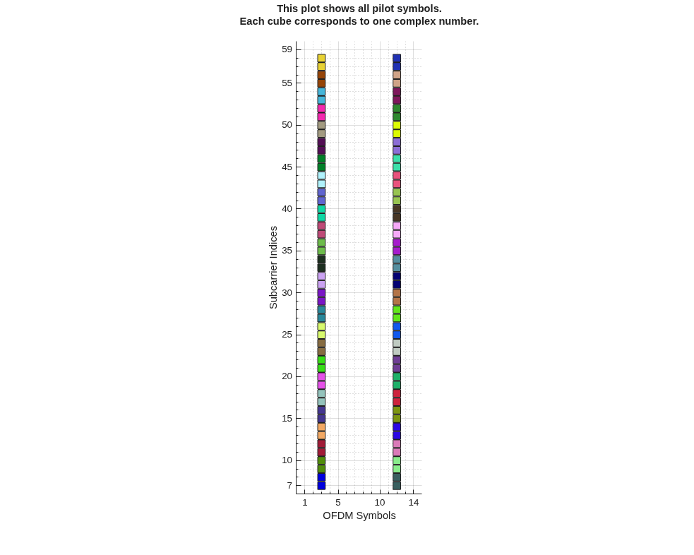
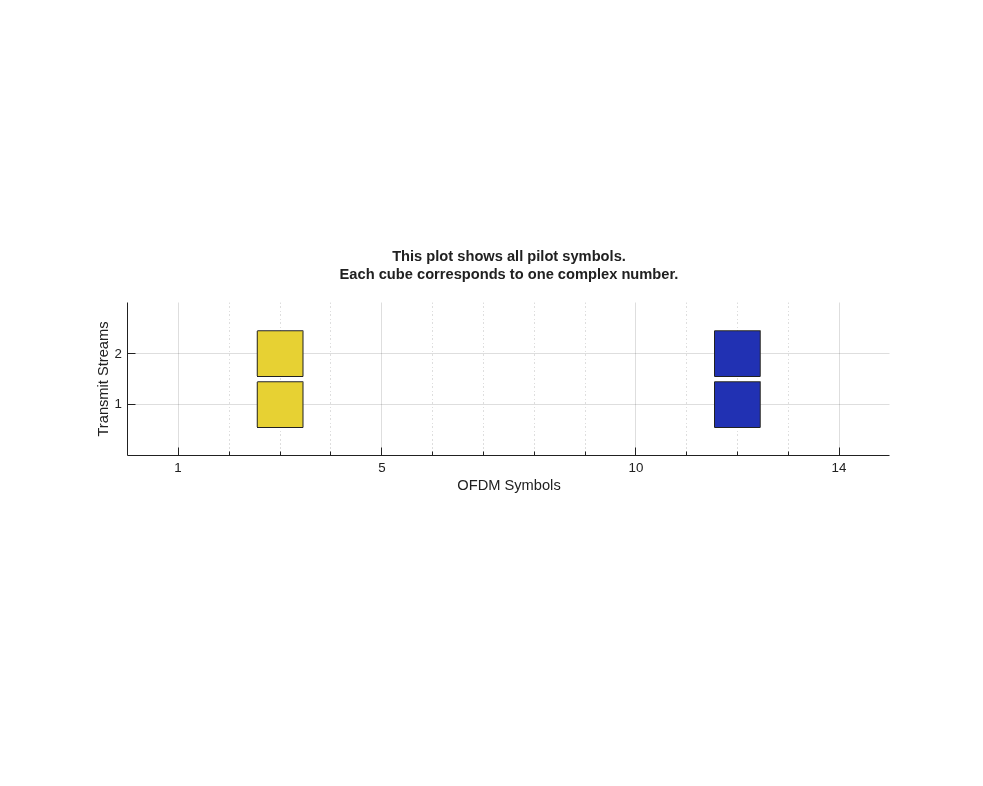
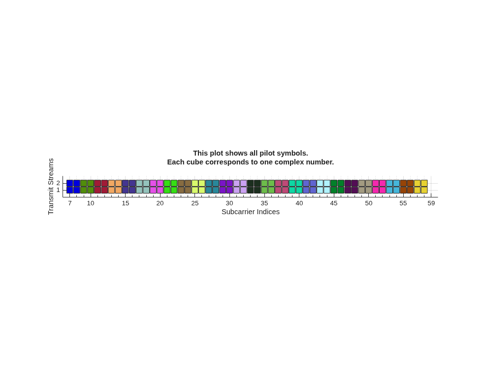
Plot cardinal views to show the OFDM grid allocations.
plot(pilotcfg)
view([90 -90]) % symbol-subcarrier view
plot(pilotcfg)
view([90 0]) % symbol-stream view
plot(pilotcfg)
view([0 0]) % subcarrier-stream view
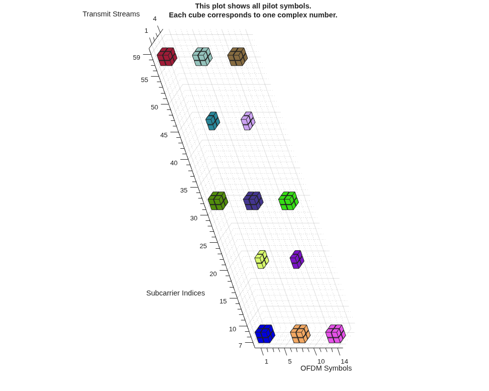
Create the pilot configuration object.
pilotcfg = ofdmPilotConfig( ... 'FFTLength', 64, ... 'NumGuardBandCarriers', [6; 5], ... 'NumSymbols', 14, ... 'NumTransmitStreams', 4, ... 'StreamGroups', {[1 2], [3 4]} );
Create pilot locations for each stream group. For the first group, create 2-by-2 pilot matrices for each of nine clusters. For the second group, create 2-by-1 pilot matrices for each of four clusters.
pilotLocations1 = ofdmPilotGrid([1 2], [1 2], [7 31 57], [1 7 13]); pilotLocations2 = ofdmPilotGrid([1 2], 1, [19 44], [4 10]);
Check the number of clusters for each group.
numClusters1 = size(pilotLocations1, 3)
numClusters1 = 9
numClusters2 = size(pilotLocations2, 3)
numClusters2 = 4
Create pilot symbols for each group (must match number of clusters).
pilotSymbols1 = randn(size(pilotLocations1, 1), ... numel(pilotcfg.StreamGroups{1}), ... numClusters1); pilotSymbols2 = randn(size(pilotLocations2, 1), ... numel(pilotcfg.StreamGroups{2}), ... numClusters2);
Assign pilots to the configuration object, pilotcfg.
pilotcfg.PilotLocations = {pilotLocations1, pilotLocations2};
pilotcfg.PilotSymbols = {pilotSymbols1, pilotSymbols2};Validate and plot. The validate function displays a return message for invalid configurations only. For valid pilot configurations no message is displayed.
validate(pilotcfg); plot(pilotcfg);
Algorithms
When you run the syntax:
pilotcfg = ofdmPilotConfig(fftlen,numGuardCarriers,numSym,numTxStreams)
The configuration object sets the pilot locations,
pilotcfg.PilotLocations to {ofdmPilotGrid(scIndices,symIndices,clusterScPos,clusterSymPos)}
as shown in this code.
n = log2(numTxStreams); clusterNumSc = 2^ceil(n/2); clusterNumSym = 2^floor(n/2); scIndices = 1:clusterNumSc; symIndices = 1:clusterNumSym; clusterScPos = (numGuardCarriers(1)+1):clusterNumSc:(fftlen-numGuardCarriers(2)+1-clusterNumSc); clusterSymPos = [3 numSym-1-clusterNumSym];
The object computes pilot symbols for each cluster of pilot locations. The pilot
symbols pilot.PilotSymbols
are stored in a 3D array. Each cluster is a full-rank matrix containing complex values
constructed from a pseudo-random sequence generator of random bits mapped to QPSK
symbols. For each cluster, a diagonal matrix of these symbols is multiplied by a
Hadamard matrix to ensure the pilot symbols for all streams are mutually
orthogonal.
pilotcfg.PilotSymbols = ... {reshape(pskmod(h(),4,pi/4,InputType='bit'),numTxStreams,1,[]) .* hadamard(numTxStreams)} h = comm.PNSequence(Polynomial='z^24 + z^23 + z^22 + z^17 + 1', ... InitialConditions=[zeros(1,18) ones(1,6)], ... SamplesPerFrame=2*numTxStreams*size(pilotcfg.PilotLocations{1},3));
References
[1] Van de Beek, J.-J., O. Edfors, M. Sandell, S. K. Wilson, and P. O. Borjesson. “On Channel Estimation in OFDM Systems." Vehicular Technology Conference, IEEE 45th, Volume 2, IEEE, 1995.
Extended Capabilities
Usage notes and limitations:
See System Objects in MATLAB Code Generation (MATLAB Coder).
Refer to the usage notes and limitations in the C/C++ Code Generation section. The same usage notes and limitations apply to GPU code generation.
Version History
Introduced in R2026a
MATLAB Command
You clicked a link that corresponds to this MATLAB command:
Run the command by entering it in the MATLAB Command Window. Web browsers do not support MATLAB commands.
选择网站
选择网站以获取翻译的可用内容,以及查看当地活动和优惠。根据您的位置,我们建议您选择:。
您也可以从以下列表中选择网站:
如何获得最佳网站性能
选择中国网站(中文或英文)以获得最佳网站性能。其他 MathWorks 国家/地区网站并未针对您所在位置的访问进行优化。
美洲
- América Latina (Español)
- Canada (English)
- United States (English)
欧洲
- Belgium (English)
- Denmark (English)
- Deutschland (Deutsch)
- España (Español)
- Finland (English)
- France (Français)
- Ireland (English)
- Italia (Italiano)
- Luxembourg (English)
- Netherlands (English)
- Norway (English)
- Österreich (Deutsch)
- Portugal (English)
- Sweden (English)
- Switzerland
- United Kingdom (English)