OSTBC Encoder
Encode input message using orthogonal space-time block code
Libraries:
Communications Toolbox /
MIMO
Description
The OSTBC Encoder block encodes an input symbol sequence using an orthogonal space-time block code (OSTBC). The block maps the input symbols block-wise and concatenates the output codeword matrices in the time domain. For more information, see OSTBC Encoding Algorithm.
Examples
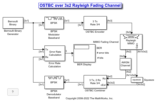
Simulate orthogonal space-time block codes (OSTBC) to achieve diversity gains in a multiple-input multiple-output (MIMO) communications system. The example shows the transmission of data over three transmit antennas and two receive antennas using independent Rayleigh fading per link.
Explore Model
The doc_ostc32 model creates a random binary signal, modulates it using a binary phase shift keying (BPSK) technique, and then encodes the waveform using a rate 3/4 orthogonal space-time block code for transmission over the fading channel. The fading channel has six independent links that result from the configuration of single-path Rayleigh fading processes. The simulation adds white Gaussian noise at the receiver, and then combines the signals from both receive antennas into a single stream for demodulation. For this combining process, the model assumes perfect knowledge of the channel gains at the receiver. The simulation compares the demodulated data with the original transmitted data and computes the bit error rate. The simulation runs until it processes 100 errors or 1e6 bits, whichever comes first.

Orthogonal Space-Time Block Code
This matrix shows the rate 3/4 code with three transmit antenna orthogonal space-time block code configured in the OSTBC Encoder block:

where  ,
,  , and
, and  correspond to the three symbol inputs for which the output is given by the matrix. The input to the OSTBC Encoder block is a 3-by-1 vector signal and the output is a 4-by-3 matrix. The number of columns in the output signal indicates the number of transmit antennas for this simulation, where the first dimension is for time. The OSTBC Combiner block outputs a 3-by-1 vector.
For the rate 3/4 OSTBC code modeled, the output signal power per time step is 3x(3/4) = 2.25W. A channel symbol carries 3 data bits, is 4 time steps long, and has a period of 3e-3 seconds. At the receiver, two antennas result in 3/2 bits per symbol per channel (antenna). In addition,

where k is the number of bits per symbol. Since the AWGN Channel block requires per-channel values for input signal power and number of bits per symbol, set the Es/No value to EbNo+10*log10(3/2) to calibrate the white Gaussian noise added in the simulation.
Performance
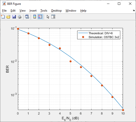
Compare the performance of the model to theoretical results by using the Bit Error Rate Analysis app. This plot compares the simulated BER for a range of Eb/No values with the theoretical results for a diversity order of six.

The theoretical and simulated results align well. The variation between theoretical and simulated results is primarily due to the simulated fading channel model having a small Doppler fade. Since the simulated channel varies slightly over the block symbols, the simulated and theoretical results show some variation.
Ports
Input
Input data, specified as a column vector or matrix of values with power-of-two slope and zero bias. For more information, see Input-to-Output Dimensions.
This port is unnamed on the block icon.
Data Types: single | double | fixed point
Complex Number Support: Yes
Output
Output data, returned as a matrix or 3-D array. For more information, see Input-to-Output Dimensions.
The output signal inherits the data type from the input signal. For fixed-point signals, the Saturate on integer overflow parameter specifies how the block handles integer overflows due to complex conjugation.
This port is unnamed on the block icon.
Data Types: single | double | fixed point
Parameters
To edit block parameters interactively, use the Property Inspector. From the Simulink® Toolstrip, on the Simulation tab, in the Prepare gallery, select Property Inspector.
Main
Number of transmit antennas, specified as 2,
3, or 4.
Symbol rate of the code, specified as 3/4 or
1/2. When you set Number of
transmit antennas to 2, the symbol rate
is 1.
Dependencies
To enable this parameter, set Number of transmit
antennas to 3 or
4.
Data Types
For fixed-point calculations, use this parameter to specify the method to be used if the magnitude of a fixed-point calculation result does not fit into the range of the data type and scaling that stores the result.
To saturate on integer overflow, select this parameter.
To wrap on integer overflow, do not select this parameter.
For more information, see Precision and Range.
Data Types: Boolean
Block Characteristics
More About
The OSTBC encoder supports time and spatial domains for OSTBC transmission and an optional dimension over which the encoding calculation is independent. This illustration indicates the supported input dimensions and resulting output dimensions.
When you input a time or spatial domain signal of size T-by-
1, the encoder outputs a (T/R)-by-N matrix.When you input a matrix of size F-by-T, the encoder outputs an F-by-(T/R)-by-N array.
Where:
R — Symbol rate of the code, as specified by the Rate parameter.
For N = 2, R must be 1.
For N = 3 or 4, R can be 3/4 or 1/2.
N — Number of transmit antennas, as specified by the Number of transmit antennas parameter. N can be 2, 3, or 4.
T — Input symbol sequence length for the time domain. The time domain length T must be a multiple of the number of symbols in each codeword matrix.
For N = 2 or R = 1/2, T must be a multiple of 2.
For R = 3/4, T must be a multiple of 3.
T/R — Symbol sequence length in time domain for the output signal.
F — Additional dimension; typically the frequency domain. The encoding is independent of this additional dimension. F can be any positive integer.
Algorithms
The OSTBC encoder algorithm implements the five different OSTBC codeword matrices shown in this table. The number of transmit antennas and the symbol rate determine the codeword matrix that the algorithm uses to encode the input data.
| Number of Transmit Antennas | Symbol Rate | OSTBC Codeword Matrix |
|---|---|---|
| 2 | 1 | |
| 3 | 1/2 | |
| 3 | 3/4 | |
| 4 | 1/2 | |
| 4 | 3/4 |
In each matrix, each (l, i) element indicates the symbol
transmitted from the ith antenna in the lth
time slot of the codeword block. Values for i are in the range
[1,N], where N is
the number of transmit antennas. Values for l are in the range
[1,L], where L is
the codeword block length.
When processing variable-size signals:
If the input signal is a column vector, the first dimension can change, but the second dimension must remain fixed at
1.If the input signal is a matrix, both dimensions can change.
Extended Capabilities
C/C++ Code Generation
Generate C and C++ code using Simulink® Coder™.
Version History
Introduced in R2009a
MATLAB Command
You clicked a link that corresponds to this MATLAB command:
Run the command by entering it in the MATLAB Command Window. Web browsers do not support MATLAB commands.
选择网站
选择网站以获取翻译的可用内容,以及查看当地活动和优惠。根据您的位置,我们建议您选择:。
您也可以从以下列表中选择网站:
如何获得最佳网站性能
选择中国网站(中文或英文)以获得最佳网站性能。其他 MathWorks 国家/地区网站并未针对您所在位置的访问进行优化。
美洲
- América Latina (Español)
- Canada (English)
- United States (English)
欧洲
- Belgium (English)
- Denmark (English)
- Deutschland (Deutsch)
- España (Español)
- Finland (English)
- France (Français)
- Ireland (English)
- Italia (Italiano)
- Luxembourg (English)
- Netherlands (English)
- Norway (English)
- Österreich (Deutsch)
- Portugal (English)
- Sweden (English)
- Switzerland
- United Kingdom (English)