Model-Free Training of AI-Based OFDM Wireless Systems
This example shows how to use a custom training loop and loss function for model-free training of an orthogonal frequency division multiplexing (OFDM) communications system.
This example also shows how to test the trained network with over-the-air (OTA) signals. The OTA testing requires these resources:
Communications Toolbox Support Package for Analog Devices ADALM-Pluto Radio
Two ADALM Pluto radios
For this example, you train and test an OFDM-based autoencoder system over a fading channel that uses an AI transmitter and receiver.
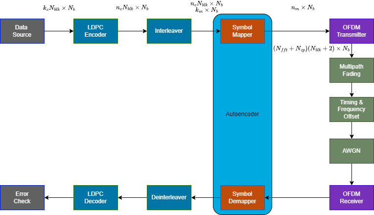
In this system, a data source outputs -by- bits, which then get encoded and interleaved. The symbol mapper in the autoencoder maps bits onto complex-valued symbols. With bins and cyclic prefix , the OFDM transmitter modulates the symbols onto multiple subcarriers and adds reference symbols and pilots. Each time the system runs, it processes a batch of size OFDM symbols. This communications link uses a single-input-single-output (SISO) configuration. The channel has multiple impairments:
Rician fading
Random propagation delay in timing
Frequency offset
Additive white Gaussian noise (AWGN)
The symbol demapper in the autoencoder maps signals from the OFDM receiver back into complex-valued symbols. For model-free training of a single carrier system over an AWGN channel, see Custom Training Loops and Loss Functions for AI-Based Wireless Systems.
Define System Parameters
Channel Coding and Interleaving
Set the code rate in the low density parity check (LDPC) encoder at 1/2 rate to process message bits and produce bit codewords. To increase the resilience of the system to deep fades, the random interleaver interleaves codewords. Later, when you configure the PFDM transmitter and receiver, you determine the codeword length, , and message length, , in conjunction with the number of subcarriers.
sysParams.codeRate = 1/2;
Autoencoder
Design a wireless autoencoder that inputs bits and outputs complex symbols, where is the number of bits per symbol. must be an integer multiple of . Set the number of blocks, , to 1.
sysParams.bitsPerSymbol =6; % Number of bits per QAM symbol sysParams.Nblk =
1; % Number of blocks
Training
Set the batch size, , to 128. Randomly select values between 5 and 16 dB. For other values of , scale the values to keep the overall training symbol error rate (SER) around 10%. Set the learning rate to 0.01. Decrease the learning rate by a factor of 0.7 every 2000 training iterations.
trainParams.Nb = 128;
trainParams.ebnoMin = 5;
trainParams.ebnoMax = 16;
trainParams.initialLearningRate = 1e-2;
trainParams.learningRateDropPeriod = 2000;
trainParams.learningRateDropFactor = 0.7;
Fading Channel
Simulate a multipath Rician fading channel with the following parameters. Set the Rician fading specular component of the Doppler shift to 0. In the next section, you account for the Doppler shift by using a random frequency offset.
chanParams.applyFading = true;
chanParams.maxDopplerShift  = 10;           % Max Doppler shift of diffuse components (Hz)
chanParams.pathDelays = [0 0.4 1.2]*1e-6;   % Discrete path delays of a three-path channel (s)
chanParams.averagePathGains = [0 -6 -9];    % Average path gains (dB)
chanParams.KFactor = 10;                    % Linear ratio of specular to diffuse power
chanParams.specDopplerShift = 0;            % Doppler shift of specular component (Hz)
                                            % Use frequency shift as Doppler
RF Impairments
The system assumes that an algorithm synchronizes the received samples in time and frequency with a residual error. The dual-chirp synchronization algorithm results in a mean frequency offset error of -19 Hz and a standard deviation of 80 Hz. The mean value of the timing error is 2.8 samples and the standard deviation is 4.5 samples. The training algorithm simulates the residual frequency and timing errors instead of simulating the synchronization algorithm.
chanParams.DualChirpSync = true;
chanParams.meanFrequencyOffset = -19;     % Mean of residual frequency offset after coarse correction
chanParams.stdFrequencyOffset = 80;       % Standard deviation of residual frequency offset
                                          % after coarse correction
chanParams.meanDelay = 2.8;               % Mean of time delay after correction
chanParams.stdDelay = 4.5;                % Standard deviation of time delay after correction
Signal-to-Noise Ratio
Calculate the modulation order and convert values to signal-to-noise ratio () values.
M = 2^sysParams.bitsPerSymbol;
disp("Modulation order is " + M)
Modulation order is 64
snrMin = convertSNR(trainParams.ebnoMin,"ebno", ...
      BitsPerSymbol=sysParams.bitsPerSymbol, ...
      CodingRate=sysParams.codeRate);
snrMax = convertSNR(trainParams.ebnoMax,"ebno", ...
      BitsPerSymbol=sysParams.bitsPerSymbol, ...
      CodingRate=sysParams.codeRate);
Simulate BLER Performance
Configure Multi-Carrier Autoencoder
To train the autoencoder to select the best constellation and demapping algorithm, you must use multiple subcarriers in the OFDM system. Use the same constellation in each subcarrier.
OFDM Transmitter and Receiver
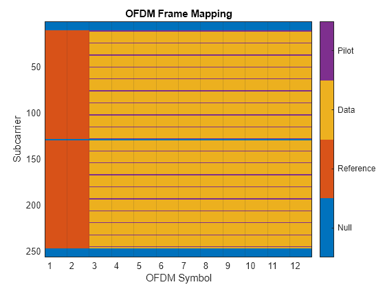
Each OFDM symbol has subcarriers and an sample cyclic prefix. The OFDM frame starts with two identical reference symbols (RS) followed by data symbols. Subcarrier spacing is 15 kHz. The output of the OFDM transmitter is an -by- array.
sysParams.Nfft = 256;                % Number of subcarriers
sysParams.Ncp  = 32;                 % Cyclic-prefix length
sysParams.scs  = 15e3;               % Subcarrier spacing
sysParams.Ngsc = 10;                 % Number of guard subcarriers
sysParams.OversamplingFactor = 2;
Calculate the sampling frequency based on the total number of subcarriers, subcarrier spacing, and oversampling factor.
Fs = sysParams.Nfft*sysParams.scs*sysParams.OversamplingFactor;   % Sampling frequency
chanParams.Fs = Fs;
Two codeword lengths are available: 648 or 1296. Decide on the number of data subcarriers and the codeword length, based on the number of subcarriers, , number of guard bands, , and number of bits per symbol, . Assume that one OFDM symbol carries one codeword.
if (sysParams.Nfft-sysParams.Ngsc)*sysParams.bitsPerSymbol < 1296
  sysParams.codewordLength = 648;   % LDPC codeword length
else
  sysParams.codewordLength = 1296;  % LDPC codeword length
end
Ndsc = sysParams.codewordLength/sysParams.bitsPerSymbol;  % Number of data subcarriers
Implement the OFDM transmitter algorithm by using the helperOFDMTransmitter object.
ofdmTx = helperOFDMTransmitter( ...
  NumSubcarriers=sysParams.Nfft, ...
  CyclicPrefixLength=sysParams.Ncp, ...
  NumDataSubcarriers=Ndsc, ...
  NumGuardSubcarriers=sysParams.Ngsc, ...
  SymbolsPerFrame=sysParams.Nblk, ...
  ReferenceSymbolModulation="QPSK", ...
  OversamplingFactor=sysParams.OversamplingFactor, ...
  DataType="single");
The OFDM receiver assumes time synchronization within one symbol duration. The receiver first does fine time synchronization by correlating the received symbol with the known reference symbol. The receiver also uses the reference symbols to estimate the frequency offset and the initial frequency domain equalizer weights. The receiver also uses the pilots to update the equalizer weights for each OFDM symbol. Implement the OFDM receiver algorithm by using the helperOFDMReceiver object.
ofdmRx = helperOFDMReceiver( ...
  NumSubcarriers=sysParams.Nfft, ...
  CyclicPrefixLength=sysParams.Ncp, ...
  NumDataSubcarriers=Ndsc, ...
  NumGuardSubcarriers=sysParams.Ngsc, ...
  SymbolsPerFrame=sysParams.Nblk, ...
  FineTimeSynchronization=true, ...
  FineFrequencyCorrection=true, ...
  ReferenceSymbolModulation="QPSK", ...
  OversamplingFactor=sysParams.OversamplingFactor, ...
  DataType="single");
The OFDM subcarrier mapping for symbols per frame equals 10.
multiCarrierResourceGrid(ofdmTx)
AI Transmitter
Use the helperTrainableSymbolMapperLayer function to map -by--by- bits into -by--by- complex symbols. Create a neural network for the transmitter by using the dlnetwork function.
txNet = dlnetwork([
  sequenceInputLayer(1,Name="Bit input",MinLength=sysParams.codewordLength*sysParams.Nblk)

  helperTrainableSymbolMapperLayer(ModulationOrder=M, ...
    BitInput=true, ...
    UnitAveragePower=true, ...
    ComplexOutput=true, ...
    Name="mod")
  ]);
AI Receiver
The receiver is a fully connected neural network with two hidden layers and an output layer. The input to the receiver is the channel impaired complex symbols in the form of a -by--by- complex-valued array and a per batch channel noise variance array in log domain with size -by-. Each hidden layer has 128 outputs followed by rectified linear unit (ReLU) activation. The output layer estimates the log-likelihood ratio (LLR) values for bits in every symbol in the form of a -by--by- array. Use the dlnetwork function to create a neural network for the receiver
rxNet = dlnetwork([
  sequenceInputLayer(1,Name="rcvd symbols",SplitComplexInputs=true, ...
                       MinLength=sysParams.codewordLength*sysParams.Nblk/sysParams.bitsPerSymbol)

  concatenationLayer(1,2,Name="demapper_concat")

  fullyConnectedLayer(128,Name="demapper_fc1")
  reluLayer(Name="demapper_relu1")

  fullyConnectedLayer(128,Name="demapper_fc2")
  reluLayer(Name="demapper_relu2")

  fullyConnectedLayer(sysParams.bitsPerSymbol,Name="demapper_fc3")
  ],Initialize=false);
noInput = sequenceInputLayer(1,Name="no",MinLength=sysParams.codewordLength*sysParams.Nblk/sysParams.bitsPerSymbol);
rxNet = addLayers(rxNet,noInput);
rxNet = connectLayers(rxNet,"no","demapper_concat/in2");
rxNet = initialize(rxNet);
Train Autoencoder Model-Free
Generate an -by- array of random data bits. The autoencoder requires input to a dlarray object that specifies "channel, batch, time" (CBT) labels. Label the first dimentaion as T for data bits, the second dimension as B for batch, and C for unused dimension,The dlarray function rearranges the dimensions.
d = dlarray(randi([0 1],sysParams.codewordLength*sysParams.Nblk, ...
  trainParams.Nb,"single"),"TBC");
Generate random SNR values between snrMax and snrMin for each element of the batch.
snr = rand(1,trainParams.Nb,"like",dlarray(single(0))) ...
      * (snrMax - snrMin) + snrMin;
If a GPU is available, move the variables to the GPU memory.
executionEnvironment = helperCheckGPUDevices();
Setting execution environment to 'cpu'
if executionEnvironment == "gpu"
  d = gpuArray(d);
  snr = gpuArray(snr);
end
Map bits into symbols using the encoder part of the autoencoder. The output of the symbol mapper is a -by--by- array.
encOut = forward(txNet,d);
Training the transmitter is optional. If you want to train the transmitter, add perturbation with nonzero variance.
trainParams.perturbationVar = 0.01;
encOutp = encOut + randn(size(encOut),'like',encOut)*sqrt(perturbationVar);
Since the OFDM transmitter expects a -by- complex-valued array, permute the dimensions. The output of the OFDM modulator is an array of -by--by-, where is one for this example. Also, calculate the signal power to use later in the awgn function.
syms = permute(extractdata(encOutp),[3 2 1]);
x = ofdmTx(syms);
S = var(x(:));
chanParams.SignalPower = gather(S);
Apply random delay to simulate the inaccuracies of the coarse timing synchronization algorithm. Also, add extra zeros at the end of the packet to account for delays in the system, such as the channel filter delay, and timing synchronization errors.
maxDelay = max(100,ceil(chanParams.meanDelay + chanParams.stdDelay*6));
delayT = round(randn()*chanParams.stdDelay+chanParams.meanDelay);
if delayT >= 0
  xd = [zeros(delayT,1,trainParams.Nb); x; zeros(maxDelay-delayT,1,trainParams.Nb)];
else
  xd = [x(-delayT+1:end,:,:); zeros(maxDelay-delayT,1,trainParams.Nb)];
end
Apply Rician fading.
fadingChan = comm.MIMOChannel( ...
  SampleRate=Fs, ...
  PathDelays=chanParams.pathDelays, ...
  AveragePathGains=chanParams.averagePathGains, ...
  KFactor=chanParams.KFactor, ...
  DirectPathDopplerShift=chanParams.specDopplerShift, ...
  MaximumDopplerShift=chanParams.maxDopplerShift, ...
  FadingDistribution="Rician", ...
  SpatialCorrelationSpecification="None", ...
  NumTransmitAntennas=1, ...
  NumReceiveAntennas=1);
xf = fadingChan(xd);
Assume that the received signal has a frequency shift due to local oscillator mismatch and motion. The dual-chirp synchronization algorithm corrects for this offset but results in a residual frequency offset. To simulate this residual frequency offset, apply a different random frequency offset to each element of the batch.
maxFrequencyOffset = 100;
deltaF = round(rand(1,trainParams.Nb)*2*maxFrequencyOffset) - maxFrequencyOffset;
rcvd = zeros(size(xf),"like",xf);
for p=1:size(x,2)
  rcvd(:,p,:) = permute(frequencyOffset(permute(xf(:,p,:),[1 3 2]),Fs,deltaF),[1 3 2]);
end
Apply a different SNR to each element of the batch. Use the convertSNR function to calculate the OFDM signal SNR based on the per subcarrier SNR.
y = awgn(rcvd,convertSNR(extractdata(snr), ...
  "snrsc",FFTLength=sysParams.Nfft,NumActiveSubcarriers=Ndsc),S);
Extract the modulated data from the OFDM symbols. The output of the OFDM receiver is an -by- array. The AI demapper expects a -by-N_b-by- complex-valued array with CBT labels. Create a dlarray object with dimension labels "TBC" that match the data format. The dlarray function permutes the data accordingly.
[encOutHatCp,noHat] = ofdmRx(y);
encOutHatC = dlarray(encOutHatCp,"TBC");
noHat = dlarray(repmat(noHat,Ndsc*sysParams.Nblk,1),"TBC");
Demap the received symbols into LLR values using the decoder part of the autoencoder.
llr = forward(rxNet,encOutHatC,noHat);
The helperMulticarrierAutoencoderRLModel function implements this processing chain. To train the OFDM-based autoencoder, use the helperOFDMAutoencoderReceiverModelLoss and helperOFDMAutoencoderTransmitterModelLoss functions, which calculate loss, gradients, and the SER.
[lossRxNet,gradientsRx,ser] = dlfeval(@helperOFDMAutoencoderRxModelLoss, ...
  txNet,rxNet,d,snr,ofdmTx,ofdmRx,chanParams);
trainParams.perturbationVar = 0.01;
[lossTxNet,gradientsTx] = dlfeval(@helperOFDMAutoencoderTxModelLoss, ...
  txNet,rxNet,d,snr,trainParams.perturbationVar,ofdmTx,ofdmRx,chanParams);
Custom Training Loop
The helperTrainModelFreeOFDMAutoencoder function implements the training algorithm from [1], which alternates between conventional training of the neural-network-based receiver and reinforcement learning (RL) training of the transmitter. Perform 7000 iterations of alternating training. Then fine-tune the receiver with 3000 iterations on only the receiver.
trainParams.numAlternatingTrainingIterations = 7000;
trainParams.numFinetuningIterations = 3000;
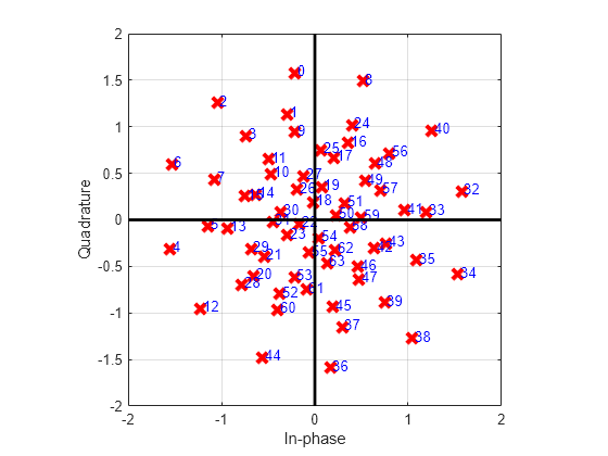
On an NVIDIA RTX A5000 GPU with compute capability of 8.6 and 24 GB of memory, training takes about an hour, with visualizations turned on. To train the network, set trainNow to true. Otherwise, this example loads pretrained networks. The constellation plot shows the learned constellation.
trainNow =false; if trainNow trainParams.showTrainingProgress = true; [txNet,rxNet,monitor] = ... helperTrainModelFreeOFDMAutoencoder(trainParams,sysParams,chanParams); else fileName = sprintf("modelfree_trained_ofdm_Nblk%dk%d_%d", ... sysParams.Nblk,sysParams.bitsPerSymbol,sysParams.codewordLength); try load(fileName,"txNet","rxNet") catch me if strcmp(me.identifier,'MATLAB:load:couldNotReadFile') error("Selected combination of Nblk, k, and d does not have pretrained " + ... "networks. Set trainNow to true (check the checkbox).") else rethrow(me) end end figure plot(txNet.Layers(2)) end
Simulate BLER Performance
Compare the performance of the model-free trained, OFDM-based autoencoder to that of a baseline system that uses QAM modulation with Gray coding and OFDM. Both systems use an LDPC outer code. Increase targetBlockErrors and maxNumBlocks to increase the accuracy of error rate estimates.
simAccuracy ="Low"; if strcmp(simAccuracy, "Low") simParams.targetBlockErrors = 100; simParams.maxNumFrames = 3000; simParams.ebnoVec = 8:4:16; else simParams.targetBlockErrors = 1000; simParams.maxNumFrames = 1e6; simParams.ebnoVec = 8:2:16; end
Because each OFDM frame contains two reference symbols followed by data symbols, sending more than one data symbol is more efficient than one data symbol per frame. Set symbolsPerFrame to 10. As the number of symbols in an OFDM frame increases, the channel estimate for the latter symbols becomes less reliable due to nonstationary channel conditions. As a result, higher values of symbolsPerFrame can result in higher error rates.
sysParams.symbolsPerFrame = 10;
Select a simulation data type. Single data types require less memory and run faster than double data types. If you have a GPU and Parallel Processing Toolbox, you can set the data type to gpuArray single to further speed up the simulations.
simParams.dataType =  "single";
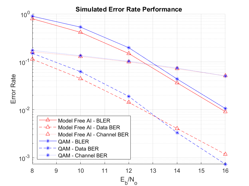
The helperModelFreeOFDMAutoencoderErrorRate script implements the link-level simulation to estimate the channel bit error rate (BER), data BER, and block error rate (BLER) for QAM, of a conventionally trained autoencoder, and for the model-free trained autoencoder. All three estimations use an OFDM-based multicarrier system over a multipath Rician fading channel with timing and frequency offset. This simulation supports results of a higher accuracy simulation.
Run the helperModelFreeOFDMAutoencoderErrorRate function to simulate the systems.
[berChan,berData,bler,berfig] = helperModelFreeOFDMAutoencoderErrorRate(txNet,rxNet, ...
  sysParams,chanParams,simParams);
Starting BLER simulation... 00:00:05.7 - Eb/No = 8.0, BER = 2.2e-01, # Blocks = [100 100], # Block Errors = [129600 129600] 00:00:10.2 - Eb/No = 12.0, BER = 1.5e-01, # Blocks = [150 150], # Block Errors = [194400 194400] 00:00:18.8 - Eb/No = 16.0, BER = 8.5e-02, # Blocks = [1590 1590], # Block Errors = [2060640 2060640]
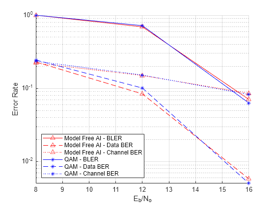
The BLER curves show that the conventional autoencoder, which has full knowledge of the differentiable channel, outperforms the baseline system by about 0.7 dB at 10% BLER. The RL-based autoencoder, which does not have the channel model, performs within 0.1 dB of the conventional autoencoder.
Measure Over-the-Air BLER Performance
Measure the over-the-air BLER performance of the system by using two SDR devices to transmit and receive the signals as shown in the following code. Run this section of the example only if the required support package and radios are available.
runSDRSection = false;
if helperIsPlutoSDRInstalled()
  radios = findPlutoRadio();
  if length(radios) > 1
    runSDRSection = true;
  else
    disp("Over-the-air tests require two ADALM-PLUTO radios. Skipping SDR test.")
  end
else
    disp("Communications Toolbox Support Package for Analog Devices ADALM-PLUTO Radio not found.")
    disp("Click Add-Ons in the Home tab of the MATLAB toolstrip to install the support package.")
    disp("Skipping OTA test.")
end
Communications Toolbox Support Package for Analog Devices ADALM-PLUTO Radio not found.
Click Add-Ons in the Home tab of the MATLAB toolstrip to install the support package.
Skipping OTA test.
Initialize the derived parameters.
symbolsPerFrame = sysParams.blocksPerFrame*sysParams.Nblk;
Ndsc = sysParams.codewordLength/sysParams.bitsPerSymbol;
Fs   = sysParams.Nfft*sysParams.scs*sysParams.OversamplingFactor;
M    = 2^sysParams.bitsPerSymbol;
Initialize the OTA transceiver. By running the helperOTATransciever function to transmit and receive the signals using two ADALM-Pluto radios.
trcv = helperOTATransciever( ...
  CenterFrequency=2e9, ...
  SampleRate=Fs, ...
  TxGain=0, ...
  RxGain=30, ...
  TransmissionPeriod=0.1);
The OTA transceiver adds a preamble and performs coarse time and frequency synchronization for each OFDM frame. Increase the number of OFDM symbols per frame to decrease the percent overhead.
release(ofdmTx)
ofdmTx.SymbolsPerFrame = symbolsPerFrame;
release(ofdmRx)
ofdmRx.SymbolsPerFrame = symbolsPerFrame;
Configure the LDPC encoder and decoder.
messageLength = sysParams.codewordLength*sysParams.codeRate;
[ldpcEncCfg,ldpcDecCfg] = helperLDPCCodeInfo(sysParams.codeRate,sysParams.codewordLength);
Initialize the random interleaver.
s = RandStream("mt19937ar",Seed=12345);
interleaverArray = randperm(s,sysParams.codewordLength*symbolsPerFrame)';
Generate random data bits.
b = randi([0 1],messageLength*sysParams.Nblk,sysParams.blocksPerFrame,"single");
Apply LDPC coding and interleaving.
br = reshape(b,messageLength,symbolsPerFrame);
bcr = ldpcEncode(br,ldpcEncCfg);
bc = simParams.dataType(reshape(bcr,sysParams.codewordLength*symbolsPerFrame,1));
bcInt = intrlv(bc,interleaverArray);
Map the bits to symbols by using the model-free trained encoder and apply OFDM modulation.
d = helperAIMod(txNet,bcInt);
x = ofdmTx(d);
Send the bits through the channel using the SDRs.
[y,snrEst] = trcv(x);
Demodulate the received OFDM signal, y. If the OFDM receiver returns valid symbols, demodulate the signal using the model-free trained decoder. Then apply deinterleaving and LDPC decoding. Measure the channel, data, and block errors.
[dHat,noHat,csi,valid] = ofdmRx(y);
if valid
  llrInt = helperAIDemod(rxNet,dHat,noHat);
  llrInt = llrInt .* repelem(csi,sysParams.bitsPerSymbol);
  llr = deintrlv(llrInt,interleaverArray);
  bcHat = llr<0;
  brHat = helperLDPCDecode(llr,ldpcDecCfg,maxNumIter);
  bHat = reshape(brHat,messageLength*sysParams.Nblk,sysParams.blocksPerFrame);
  numChanErrors = sum(bc~=bcHat,'all')
  numDataErrors = sum(b~=bHat,'all')
  numBlockErrors = sum(any(b~=bHat))
end
The helperModelFreeOFDMAutoencoderOTA function implements this algorithm within a loop to estimate the error rates. Increase targetBlockErrors and maxNumBlocks to increase the accuracy of error rate estimates. A sample run of this function with two radios shows the results where the two radios face each other with a dominant line-of-sight path.
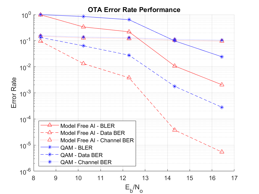
Select transmitter gain values to obtain estimated Eb/No values in the range of 8 to 16 dB.
if runSDRSection simAccuracy ="Low"; if strcmp(simAccuracy, "Low") simParams.maxNumFrames = 100; simParams.targetBlockErrors = 10; simParams.txGainVec = -46:4:-38; else simParams.maxNumFrames = 1e6; simParams.targetBlockErrors = 100; simParams.txGainVec = -46:2:-38; end [berChan,berData,bler,blerPlotter] = helperModelFreeOFDMAutoencoderOTA( ... txNet,rxNet,sysParams,simParams); end
Further Exploration
In this example, you implement an OFDM-based multicarrier communications system where the symbols carried over the subcarriers are obtained by training an autoencoder. You simulate the system BLER performance over a link with an LDPC outer code. To explore the system performance further, try different fading profiles such as Rayleigh fading. Alternatively, use standards-based channels such as nrCDLChannel, nrTDLChannel, and nrHSTChannel. Vary the number of bits per symbol, bitsPerSymbol, codeword length, codewordLength, and number of blocks, .
For each new case, adjust the training parameters listed in the Training Parameters section.
References
[1] F. Ait Aoudia and J. Hoydis, “Model-Free Training of End-to-End Communication Systems,” in IEEE Journal on Selected Areas in Communications, vol. 37, no. 11, pp. 2503-2516, Nov. 2019, doi: 10.1109/JSAC.2019.2933891.
Local Functions
OFDM Subcarrier Mapping
Plot the OFDM subcarrier mapping for a frame that consists of two reference symbols, followed by Nblk data symbols. Each symbol has guard bands and a null at the DC together with pilot symbols.
function multiCarrierResourceGrid(ofdmTx)
NULL = 1;
REFERENCE = 2;
DATA = 3;
PILOT = 4;
Nfft = ofdmTx.NumSubcarriers;
Nblk = 10;
rg = zeros(Nfft,Nblk+2);
ofdmInfo = info(ofdmTx);
rg(ofdmInfo.DataIndices,3:Nblk+2) = DATA;
rg(ofdmInfo.NullIndices,3:Nblk+2) = NULL;
rg(ofdmInfo.PilotIndices,3:Nblk+2) = PILOT;
rg([ofdmInfo.DataIndices;ofdmInfo.PilotIndices],1:2) = REFERENCE;
figure
co = colororder;
colormap(co(1:4,:))
image(rg)
ax = gca;
ax.XGrid = "on";
ax.XTick = 0.5:11.5;
tickLabels = cell(1,Nblk+2);
for p=1:Nblk+2
  tickLabels{p} = "    " + p;
end
ax.XTickLabel = tickLabels;
ax.XTickLabelRotation = 0;
ax.TickDir = "none";
cb = colorbar;
cb.Ticks = 1.5:4.5;
cb.TickLabels = ["Null","Reference","Data","Pilot"];
xlabel("OFDM Symbol")
ylabel("Subcarrier")
title("OFDM Frame Mapping")
end
See Also
dpdPreprocessor | comm.MIMOChannel