Top-Down Design of RF Receiver
This example shows how to design an RF receiver for a ZigBee-like application using a top-down methodology.
This example:
Specifies high-level requirements first to derive system-level or design specifications before allocating a gain, nonlinearity, and noise budget to each component in the RF receiver using the RF Budget Analyzer (RF Toolbox) app.
Verifies the bit error rate (BER) of an ideal reference design, before adding impairments and assessing their impact on the overall performance.
Verifies the bit error rate (BER) of an impairment-free design, then analyzes BER performance after the addition of impairment models.
Uses the RF Budget Analyzer App to rank the elements contributing to the noise and nonlinearity budget.
Integrate antenna and phase shifter to the receiver design.
Design Specifications
The RF receiver in this example uses these design specifications.
Data rate = 250 kbps
OQPSK modulation with half sine pulse shaping, as specified in IEEE® 802.15.4 standard for the physical layer of ZigBee®
Direct-sequence spread spectrum with chip rate = 2 Mchips/s
Sensitivity specification = – 100 dBm
BER specification = 1e-4
10-bit analog-to-digital converter (ADC) a saturation power of 0 dBm
To create fully standard-compliant ZigBee waveforms, you can use Communications Toolbox™.
Design Workflow
The workflow to design the RF receiver using the top-down approach consists of these four steps.
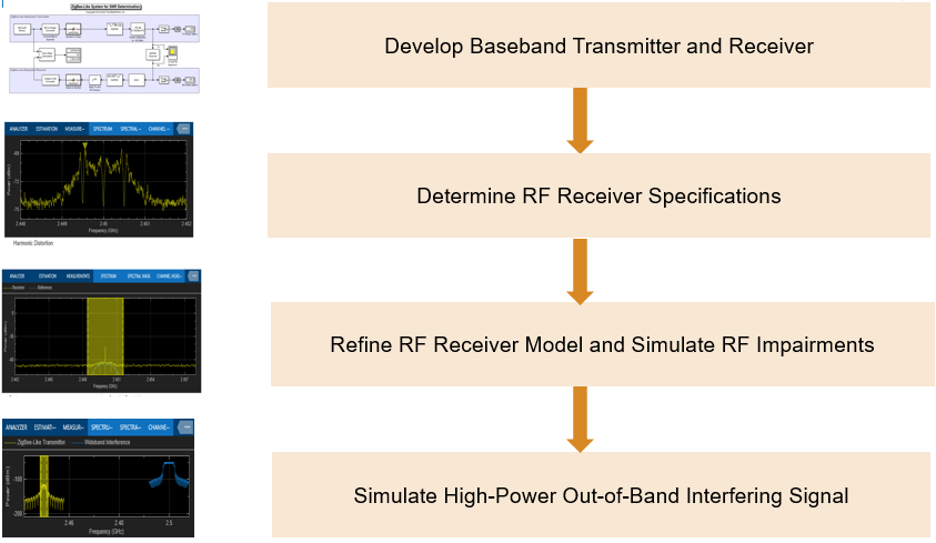
Step 1: Develop Baseband Transmitter and Receiver
In this step, you will:
Model a ZigBee-like baseband transmitter for waveform generation
Model a ZigBee-like baseband receiver model for measuring the BER
Use a link-level idealized receiver model to determine SNR that helps you achieve the target BER of 1e-4.
For more information, see the Develop ZigBee-Like Baseband Transmitter and Receiver (RF Blockset) example.
Step 2: Determine the RF Receiver Specifications
In this step, you will:
Determine the noise figure (NF) and gain (G) of the RF receiver using the ADC specifications and SNR you determined in step 1.
Verify the BER and measure the corresponding chip error rate (ChER) to speed up the simulation.
For more information, see the Determine RF Receiver Specifications (RF Blockset) example.
Step 3: Refine the RF Receiver Model and Simulate RF Impairments
In this step, you will:
Refine the architecture of the of RF receiver and derive the specifications of its individual components based on the RF budget analysis.
Create a circuit envelope model of the RF receiver using direct-conversion architecture.
Use the circuit envelope model to simulate RF impairments such as phase noise, nonlinearity, impedance mismatch, and finite local oscillator (LO) isolation.
For more information, see the Refine RF Receiver Model and Simulate RF Impairments (RF Blockset) example.
Step 4: Simulate High-Power Out-of-Band Interfering Signal
In this step, you will:
Add a high-power out-of-band interfering signal and perform multicarrier simulation.
Determine the specifications of the DC offset cancellation algorithm.
For more information, see the Simulate High-Power Out-of-Band Interfering Signal (RF Blockset) example.
Step 5: Integrate Antenna Into RF Receiver
In this step, you will:
Integrate a simple dipole antenna into the system-level model of the RF receiver and understand the impact of polarization mismatch.
Design a dual polarized antenna, analyze its performance using EM analysis, and integrate it in the system-level model of the RF receiver.
Design a Wilkinson combiner and integrate it together with the dual polarized antenna into the system-level model.
For more information, see the Integrate Antenna Into RF Receiver (RF Blockset) example.
Step 6: Integrate Phase Shifter Into RF Receiver
In this step, you will:
Build the phase shifter using a distributed PCB element, and combine it on the PCB together with the Wilkinson splitter.
Perform an EM analysis and determine S-parameters of the phase shifter and then integrate it in the system-level model of the RF receiver.
For more information, see the Integrate Phase Shifter Into RF Receiver (RF Blockset) example.