Main Content

TuningGoal.Overshoot

Overshoot constraint for control system tuning

Description

Use TuningGoal.Overshoot to limit the overshoot in the step response from specified inputs to specified outputs of a control system. Use this tuning goal for control system tuning with tuning commands such as systune or looptune.

Creation

Description

Req = TuningGoal.Overshoot(inputname,outputname,maxpercent) creates a tuning goal for limiting the overshoot in the step response between the specified signal locations. The scalar maxpercent specifies the maximum overshoot as a percentage.

When you use TuningGoal.Overshoot for tuning, the software maps overshoot constraints to peak gain constraints assuming second-order system characteristics. Therefore, the mapping is only approximate for higher-order systems. In addition, this tuning goal cannot reliably reduce the overshoot below 5%.

example

Input Arguments

expand all

Input signals for the tuning goal, specified as a character vector or, for multiple-input tuning goals, a cell array of character vectors.

  • If you are using the tuning goal to tune a Simulink® model of a control system, then inputname can include:

    • Any model input.

    • Any linear analysis point marked in the model.

    • Any linear analysis point in an slTuner (Simulink Control Design) interface associated with the Simulink model. Use addPoint (Simulink Control Design) to add analysis points to the slTuner interface. Use getPoints (Simulink Control Design) to get the list of analysis points available in an slTuner interface to your model.

    For example, suppose that the slTuner interface contains analysis points u1 and u2. Use 'u1' to designate that point as an input signal when creating tuning goals. Use {'u1','u2'} to designate a two-channel input.

  • If you are using the tuning goal to tune a generalized state-space (genss) model of a control system, then inputname can include:

    • Any input of the genss model

    • Any AnalysisPoint location in the control system model

    For example, if you are tuning a control system model, T, then inputname can be any input name in T.InputName. Also, if T contains an AnalysisPoint block with a location named AP_u, then inputname can include 'AP_u'. Use getPoints to get a list of analysis points available in a genss model.

    If inputname is an AnalysisPoint location of a generalized model, the input signal for the tuning goal is the implied input associated with the AnalysisPoint block:

For more information about analysis points in control system models, see Mark Signals of Interest for Control System Analysis and Design.

Output signals for the tuning goal, specified as a character vector or, for multiple-output tuning goals, a cell array of character vectors.

  • If you are using the tuning goal to tune a Simulink model of a control system, then outputname can include:

    • Any model output.

    • Any linear analysis point marked in the model.

    • Any linear analysis point in an slTuner (Simulink Control Design) interface associated with the Simulink model. Use addPoint (Simulink Control Design) to add analysis points to the slTuner interface. Use getPoints (Simulink Control Design) to get the list of analysis points available in an slTuner interface to your model.

    For example, suppose that the slTuner interface contains analysis points y1 and y2. Use 'y1' to designate that point as an output signal when creating tuning goals. Use {'y1','y2'} to designate a two-channel output.

  • If you are using the tuning goal to tune a generalized state-space (genss) model of a control system, then outputname can include:

    • Any output of the genss model

    • Any AnalysisPoint location in the control system model

    For example, if you are tuning a control system model, T, then outputname can be any output name in T.OutputName. Also, if T contains an AnalysisPoint block with a location named AP_u, then outputname can include 'AP_u'. Use getPoints to get a list of analysis points available in a genss model.

    If outputname is an AnalysisPoint location of a generalized model, the output signal for the tuning goal is the implied output associated with the AnalysisPoint block:

For more information about analysis points in control system models, see Mark Signals of Interest for Control System Analysis and Design.

Maximum percent overshoot, specified as a scalar value. For example, the following code specifies a maximum 5% overshoot in the step response from 'r' to 'y'.

Req = TuningGoal.Overshoot('r','y',5);

TuningGoal.OverShoot cannot reliably reduce the overshoot below 5%.

Properties

expand all

Maximum percent overshoot, specified as a scalar value. For example, the scalar value 5 means the overshoot should not exceed 5%. The initial value of the MaxOvershoot property is set by the maxpercent input argument when you construct the tuning goal.

Reference signal scaling, specified as a vector of positive real elements.

For a MIMO tracking requirement, when the choice of units results in a mix of small and large signals in different channels of the response, use this property to specify the relative amplitude of each entry in the vector-valued step input. This information is used to scale the off-diagonal terms in the transfer function from reference to tracking error. This scaling ensures that cross-couplings are measured relative to the amplitude of each reference signal.

For example, suppose that Req is a tuning goal that signals {'y1','y2'} track reference signals {'r1','r2'}. Suppose further that you require the outputs to track the references with less than 10% cross-coupling. If r1 and r2 have comparable amplitudes, then it is sufficient to keep the gains from r1 to y2 and r2 and y1 below 0.1. However, if r1 is 100 times larger than r2, the gain from r1 to y2 must be less than 0.001 to ensure that r1 changes y2 by less than 10% of the r2 target. To ensure this result, set the InputScaling property as follows.

Req.InputScaling = [100,1];

This tells the software to take into account that the first reference signal is 100 times greater than the second reference signal.

The default value, [] , means no scaling.

Input signal names, specified as a cell array of character vectors that identify the inputs of the transfer function that the tuning goal constrains. The initial value of the Input property is set by the inputname input argument when you construct the tuning goal.

Output signal names, specified as a cell array of character vectors that identify the outputs of the transfer function that the tuning goal constrains. The initial value of the Output property is set by the outputname input argument when you construct the tuning goal.

Models to which the tuning goal applies, specified as a vector of indices.

Use the Models property when tuning an array of control system models with systune, to enforce a tuning goal for a subset of models in the array. For example, suppose you want to apply the tuning goal, Req, to the second, third, and fourth models in a model array passed to systune. To restrict enforcement of the tuning goal, use the following command:

Req.Models = 2:4;

When Models = NaN, the tuning goal applies to all models.

Feedback loops to open when evaluating the tuning goal, specified as a cell array of character vectors that identify loop-opening locations. The tuning goal is evaluated against the open-loop configuration created by opening feedback loops at the locations you identify.

If you are using the tuning goal to tune a Simulink model of a control system, then Openings can include any linear analysis point marked in the model, or any linear analysis point in an slTuner (Simulink Control Design) interface associated with the Simulink model. Use addPoint (Simulink Control Design) to add analysis points and loop openings to the slTuner interface. Use getPoints (Simulink Control Design) to get the list of analysis points available in an slTuner interface to your model.

If you are using the tuning goal to tune a generalized state-space (genss) model of a control system, then Openings can include any AnalysisPoint location in the control system model. Use getPoints to get the list of analysis points available in the genss model.

For example, if Openings = {'u1','u2'}, then the tuning goal is evaluated with loops open at analysis points u1 and u2.

Name of the tuning goal, specified as a character vector.

For example, if Req is a tuning goal:

Req.Name = 'LoopReq';

Examples

collapse all

Create a tuning goal that limits the overshoot of the step response from signals named 'r' to 'y' in a control system to 10 percent.

Req = TuningGoal.Overshoot('r','y',10);

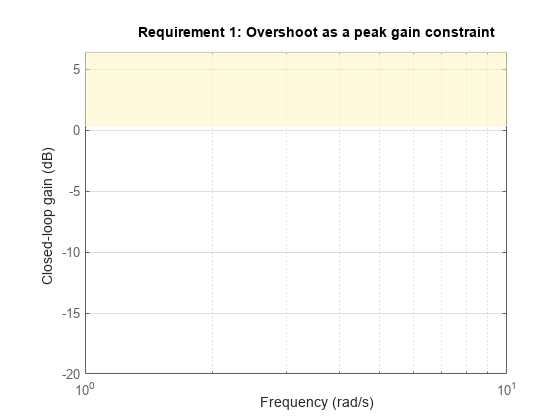
The overshoot tuning goal is evaluated as a constraint on the peak system gain, assuming second-order model characteristics (see Algorithms). Visualizing the tuning goal shows a shaded area where the target peak gain is exceeded.

viewGoal(Req)

MATLAB figure

If you visualize the tuning goal with a tuned system, the plot includes the corresponding system response.

Configure other characteristics of the tuning goal by setting properties. For instance, configure the tuning goal to apply only to the second model in a model array to tune. Also, configure it to be evaluated with a loop open at an analysis point in the control system called OuterLoop.

Req.Models = 2;
Req.Openings = 'OuterLoop';

Tips

  • This tuning goal imposes an implicit stability constraint on the closed-loop transfer function from Input to Output, evaluated with loops opened at the points identified in Openings. The dynamics affected by this implicit constraint are the stabilized dynamics for this tuning goal. The MinDecay and MaxRadius options of systuneOptions control the bounds on these implicitly constrained dynamics. If the optimization fails to meet the default bounds, or if the default bounds conflict with other requirements, use systuneOptions to change these defaults.

Algorithms

When you tune a control system using a TuningGoal, the software converts the tuning goal into a normalized scalar value f(x). x is the vector of free (tunable) parameters in the control system. The software then adjusts the parameter values to minimize f(x), or to drive f(x) below 1 if the tuning goal is a hard constraint.

For TuningGoal.Overshoot, f(x) reflects the relative satisfaction or violation of the goal. The percent deviation from f(x) = 1 roughly corresponds to the percent deviation from the specified overshoot target. For example, f(x) = 1.2 means the actual overshoot exceeds the target by roughly 20%, and f(x) = 0.8 means the actual overshoot is about 20% less than the target.

TuningGoal.Overshoot uses T as a proxy for the overshoot, based on second-order model characteristics. Here, T is the closed-loop transfer function that the tuning goal constrains. The overshoot is tuned in the range from 5% (T = 1) to 100% (T). TuningGoal.Overshoot is ineffective at forcing the overshoot below 5%.

Version History

Introduced in R2016a

expand all