View and Change Block Parameterization in Control System Tuner
Control System Tuner parameterizes every block that you designate for tuning.
When you tune a Simulink® model, Control System Tuner automatically assigns a default parameterization to tunable blocks in the model. The default parameterization depends on the type of block. For example, a PID Controller block configured for PI structure is parameterized by proportional gain and integral gain as follows:
Kp and Ki are the tunable parameters whose values are optimized to satisfy your specified tuning goals.
When you tune a predefined control architecture or a MATLAB® (generalized state-space) model, you define the parameterization of each tunable block when you create it at the MATLAB command line. For example, you can use
tunablePIDto create a tunable PID block.
Control System Tuner lets you view and change the parameterization of any block to be tuned. Changing the parameterization can include changing the structure or current parameter values. You can also designate individual block parameters fixed (non-tunable) or limit their tuning range.
View Block Parameterization
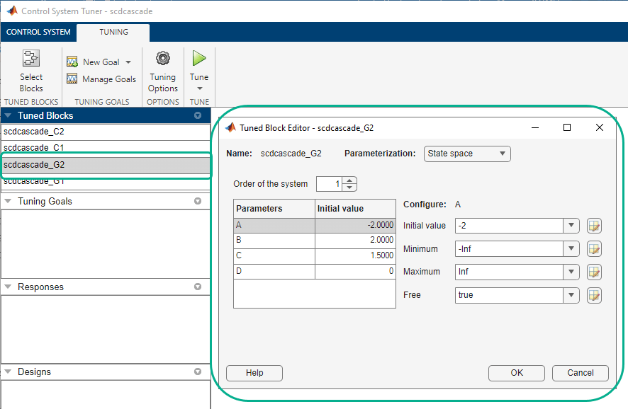
To access the parameterization of a block that you have designated as a tuned block, in the Data Browser, in the Tuned Blocks area, double-click the name of a block. The Tuned Block Editor dialog box opens, displaying the current block parameterization.

The fields of the Tuned Block Editor display the type of
parameterization, such as PID,
State-Space, or Gain. For more
specific information about the fields, click ![]() .
.
Note
To find a tuned block in the Simulink model, right-click the block name in the Data Browser and select Highlight.
Fix Parameter Values or Limit Tuning Range
You can change the current value of a parameter, fix its current value (make the parameter nontunable), or limit the parameter’s tuning range.
To change a current parameter value, type a new value in its text box. Alternatively,
click ![]() to use a variable editor to change the current value. If
you attempt to enter an invalid value, the parameter returns to its previous value.
to use a variable editor to change the current value. If
you attempt to enter an invalid value, the parameter returns to its previous value.
Click ![]() to access and edit additional properties of each
parameter.
to access and edit additional properties of each
parameter.

Minimum — Minimum value that the parameter can take when the control system is tuned.
Maximum — Maximum value that the parameter can take when the control system is tuned.
Free — When the value is
true, Control System Toolbox™ tunes the parameter. To fix the value of the parameter, set Free tofalse.
For array-valued parameters, you can set these properties independently for each entry
in the array. For example, for a vector-valued gain of length 3, enter [1 10
100] to set the current value of the three gains to 1, 10, and 100 respectively.
Alternatively, click ![]() to use a variable editor to specify such values.
to use a variable editor to specify such values.
For vector or matrix-valued parameters, you can use the Free
parameter to constrain the structure of the parameter. For example, to restrict a
matrix-valued parameter to be a diagonal matrix, set the current values of the off-diagonal
elements to 0, and set the corresponding entries in Free to
false.
Custom Parameterization
When tuning a control system represented by a Simulink model or by a Predefined Feedback Architecture, you can specify a custom
parameterization for any tuned block using a generalized state-space
(genss) model. To do so, create and configure a
genss model in the MATLAB workspace that has the desired parameterization, initial parameter values, and
parameter properties. In the Change parameterization dialog box, select
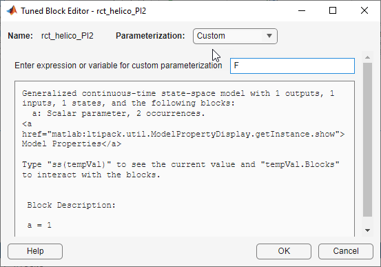
Custom. In the Parameterization area, the
variable name of the genss model.
For example, suppose you want to specify a tunable low-pass filter, F
= a/(s +a), where a is the tunable
parameter. First, at the MATLAB command line, create a tunable genss model that
represents the low-pass filter structure.
a = realp('a',1);
F = tf(a,[1 a]);
F =
Generalized continuous-time state-space model with 1 outputs, 1 inputs,
1 states, and the following blocks:
a: Scalar parameter, 2 occurrences.
Type "ss(F)" to see the current value, "get(F)" to see all properties, and
"F.Blocks" to interact with the blocks.
Then, in the Tuned Block Editor, enter F in the
Parameterization area.

When you specify a custom parameterization for a Simulink block, you might not be able to write the tuned block value back to the Simulink model. When writing values to Simulink blocks, Control System Tuner skips blocks that cannot represent the tuned value in a straightforward and lossless manner. For example, if you reparameterize a PID Controller Simulink block as a third-order state-space model, Control System Tuner will not write the tuned value back to the block.
Block Rate Conversion
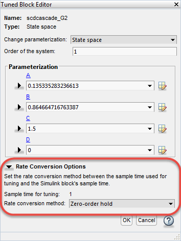
When Control System Tuner writes tuned parameters back to the Simulink model, each tuned block value is automatically converted from the sample time used for tuning, to the sample time of the Simulink block. When the two sample times differ, the Tuned Block Editor contains additional rate conversion options that specify how this resampling operation is performed for the corresponding block.

By default, Control System Tuner performs linearization and tuning in continuous time (sample time = 0). You can specify discrete-time linearization and tuning and change the sample time. To do so, on the Control System tab, click Linearization Options. Sample time for tuning reflects the sample time specified in the Linearization Options dialog box.
The remaining rate conversion options depend on the parameterized block.
Rate Conversion for Parameterized PID Blocks
For parameterization of continuous-time PID Controller and PID Controller (2-DOF) blocks, you can independently specify the rate-conversion methods as discretization formulas for the integrator and derivative filter. Each has the following options:
Trapezoidal(default) — Integrator or derivative filter discretized as(Ts/2)*(z+1)/(z-1), whereTsis the target sample time.Forward Euler—Ts/(z-1).Backward Euler—Ts*z/(z-1).
For more information about PID discretization formulas, see Discrete-Time Proportional-Integral-Derivative (PID) Controllers.
For discrete-time PID Controller and PID Controller (2-DOF) blocks, you set the integrator and derivative filter methods in the block dialog box. You cannot change them in the Tuned Block Editor.
Rate Conversion for Other Parameterized Blocks
For blocks other than PID Controller blocks, the following rate-conversion methods are available:
Zero-order hold— Zero-order hold on the inputs. For most dynamic blocks this is the default rate-conversion method.Tustin— Bilinear (Tustin) approximation.Tustin with prewarping— Tustin approximation with better matching between the original and rate-converted dynamics at the prewarp frequency. Enter the frequency in the Prewarping frequency field.First-order hold— Linear interpolation of inputs.Matched(SISO only) — Zero-pole matching equivalents.
For more detailed information about these rate-conversion methods, see Continuous-Discrete Conversion Methods.
Blocks with Fixed Rate Conversion Methods
For the following blocks, you cannot set the rate-conversion method in the Tuned Block Editor.
Discrete-time PID Controller and PID Controller (2-DOF) block. Set the integrator and derivative filter methods in the block dialog box.
Gain block, because it is static.
Transfer Fcn Real Zero block. This block can only be tuned at the sample time specified in the block.
Block that has been discretized using the Model Discretizer. Sample time for this block is specified in the Model Discretizer itself.