compositeLaneSpec
Description
The compositeLaneSpec object combines an array of lanespec objects
to create a road with multiple road segments that have different lane
specifications.
Creation
To define composite lane specifications, follow these steps:
Create an array of
lanespecobjects. The number oflanespecobjects defines the number of road segments in a road. Eachlanespecobject contains the lane specifications for one road segment.Create a composite lane specification object,
compositeLaneSpec, to combine the lane specifications, using one of the syntaxes shown here. By default, the function assumes each road segment is of equal range.To vary the range for each road segment, use the
SegmentRangeproperty of thecompositeLaneSpecobject.To define the connection between two road segments, use the
Connectorproperty of thecompositeLanespecobject.Add the
compositeLaneSpecobject to the driving scenario using theroadfunction.
Description
clspec = compositeLaneSpec(lsArray)lsArray.
For example, create a composite lane specification object,
compositeLaneSpec, to combine the lane specifications of two road
segments with two and three lanes,
respectively.
lsArray = [lanespec(2) lanespec(3)];
clspec = compositeLaneSpec(lsArray);
clspec = compositeLaneSpec(lsArray,Name,Value)'SegmentRange',[0.6 0.4] specifies that the normalized ranges of two
road segments are 0.6 and 0.4, respectively.
Properties
This property is read-only.
Lane specifications of road segments, specified as a 1-by-N array
of lanespec
objects. N is the number of lane specifications. You must specify at
least two lanespec objects to create a road with multiple lane
specifications. Each lanespec object represents a distinct road
segment. As such, the number of lanespec objects defines the number of
road segments in a road.
You must set this property using the lsArray input argument
when you create the object. To create lane specification objects, use the lanespec
function.
Example: [lanespec(2) lanespec(3)] defines the lane specifications
for a road with two segments. The first road segment has two lanes and the second
segment has three lanes.
Range of each road segment, specified as an N-element numeric
vector with normalized values in the range (0, 1). N is the number of
lanespec objects in the LaneSpecification
property. The sum of the elements of the vector must be equal to
1.
The default range value of each road segment is 1/N. For example,
if the LaneSpecification property defines the lane specifications
for two road segments, then the default range value for each road segment is
1/2, meaning that SegmentRange = [0.5
0.5].
Example: [0.4 0.3 0.3]
Data Types: single | double
Road segment connectors, specified as a laneSpecConnector object or 1-by-M array of
laneSpecConnector objects. M is the number of road
segment connectors. For a road with N segments, M
= N – 1. When specified as only one object, the same specifications
apply to all M connectors of the road.
The laneSpecConnector object specifies these properties for
connecting a pair of road segments. You can specify the properties to the
laneSpecConnector creation function as name-value arguments.
TaperShape— Specifies the shape of a taper connecting two road segments as either'Linear'or'None'. Specify'None'when you want a step change while adding or dropping lanes between road segments. The default value ofTaperShapeis'Linear'.TaperLength— Specifies the length of a taper in meters. The default value ofTaperLengthis the smaller of241meters or75percent of the length of the road segment containing the taper.Position— Specifies the edge of the road from which to add or drop lanes. You can specify the connector position as'Right','Left', or'Both'.
Example: [laneSpecConnector('Position','Left')
laneSpecConnector('TaperLength',20)]
Note
The taper is part of the lower numbered road segment within the pair. For more information about the order for numbering the road segments, see Composite Lane Specification.
Road segment connector specifications must conform with lane specifications and segment range values. Otherwise, the function resets the connector specifications with valid values. For example, if you specify a
TaperLengthlarger than the length of the corresponding road segment, the function resets the taper length with a value that is75percent of the length of the corresponding road segment.
Examples
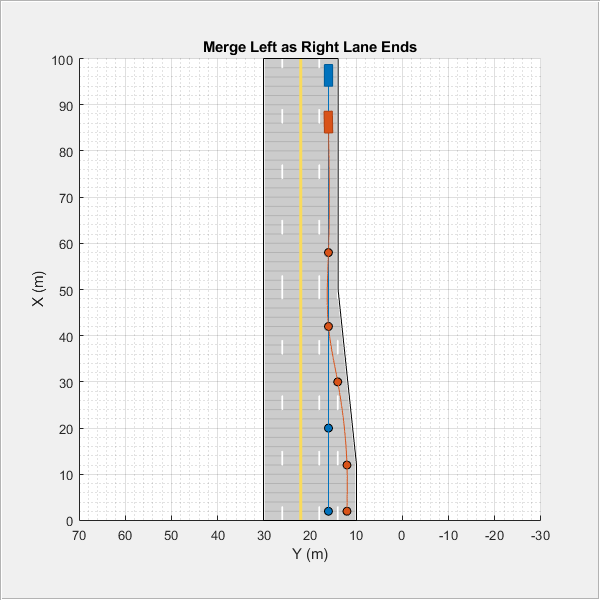
Create a driving scenario with merging traffic. The road in the driving scenario has two lane specifications and the traffic merges to the left as the right lane ends.
Create Road with Two Lane Specifications
Create a driving scenario. Specify the road centers with draw directions from bottom-to-top.
scenario = drivingScenario('StopTime',5);
roadCenters = [0 20; 100 20];
Define the lane specifications for a pair of two-way road segments. The first road segment has five lanes and the second road segment has four lanes. Notice that the rightmost lane drops from the second lane specification.
ls1 = lanespec([2 3],'Width',4);
ls2 = lanespec([2 2],'Width',4);
lsArray = [ls1 ls2];
Create a composite lane specification object and add the road to the driving scenario. The composite lane specification object determines the position at which the lane drops from the lsArray input argument. The object defaults to the linear taper shape and a taper length of 75% of the length of the first road segment.
clspec = compositeLaneSpec(lsArray);
road(scenario,roadCenters,'Lanes',clspec);
Plot the driving scenario. The scenario renders the road segments in the draw direction of the road, from bottom-to-top.
figMark = figure;
set(figMark,'Position',[0 0 600 600])
hPlot = axes(figMark);
plot(scenario,'Parent',hPlot)
title('Two-way Road Dropping Rightmost Lane')

Simulate Vehicle Lane Change
Add an ego vehicle to the scenario. Specify waypoints and a constant speed value to set its trajectory along the middle forward lane.
egoVehicle = vehicle(scenario,'ClassID',1,'Position',[2 16 0]);
waypoints = [2 16; 20 16; 95 16];
speed = 30;
smoothTrajectory(egoVehicle,waypoints,speed)
Add another vehicle to the scenario. Set the trajectory for the vehicle such that it travels in the rightmost lane and then merges to the left before the lane ends.
car = vehicle(scenario,'ClassID',1,'Position',[2 12 0]);
waypoints = [2 12; 12 12; 30 14; 42 16; 58 16; 85 16];
speed = 20;
smoothTrajectory(car,waypoints,speed)
Create a custom figure window and plot the scenario.
close all
figScene = figure;
set(figScene,'Position',[0 0 600 600])
hPanel = uipanel(figScene);
hPlot = axes(hPanel);
plot(scenario,'Waypoints','on','Parent',hPlot)
title('Merge Left as Right Lane Ends')

while advance(scenario)
    pause(0.01)
end
Create a road with multiple lane specifications and add one lane to the left of a one-way road.
Create a driving scenario. Specify the road centers for a straight, 100-meter road with draw direction from left-to-right.
scenario = drivingScenario;
roadCenters = [20 100; 20 0];
Define an array of lane specifications for two one-way road segments. The first road segment has two lanes and the second road segment has three lanes.
lsArray = [lanespec(2) lanespec(3)];
Define a road segment connector object. To add the third lane to the left side of the second road segment, specify the position property. Specify a taper length less than the length of the first road segment. Both the road segments are 50 meters long since, by default, the total road length of 100 meters is divided equally between the specified road segments.
lc = laneSpecConnector('Position','Left','TaperLength',30);
Create a composite lane specification object.
clspec = compositeLaneSpec(lsArray,'Connector',lc);Add a road to the driving scenario and display the road. The scenario renders the road segments in the draw direction of the road, from left-to-right.
road(scenario,roadCenters,'Lanes',clspec);
plot(scenario)
title('Road with Multiple Lane Specifications')

Create an empty driving scenario. Specify the road centers for a curved road.
scenario = drivingScenario;
roadCenters = [-20 22; 0 22; 18.8 15.8; 22 0; 22 -20];
Define the lane specifications for three two-way road segments. Notice that all the road segments have the same number of lanes. However, the second road segment has a greater lane width (4.6 meters) to widen the road along the curve. The other two road segments have the default lane width of 3.6 meters.
lsArray = [lanespec([1 1]) lanespec([1 1],'Width',4.6) lanespec([1 1])];Define normalized lengths for each road segment. Notice that the sum of normalized lengths is 1, and the length of the vector matches the number of lane specification objects.
range = [0.25 0.65 0.1];
Create a road segment connector object. Since the same specifications apply to both segment connectors for the three road segments, create only one laneSpecConnector object. Since you are neither adding nor dropping lanes, do not define the position property of the road segment connector.
lc = laneSpecConnector('TaperLength',14);Create a composite lane specification object and add the road to the driving scenario.
clspec = compositeLaneSpec(lsArray,'Connector',lc,'SegmentRange',range);
road(scenario,roadCenters,'Lanes',clspec);
Plot the driving scenario.
plot(scenario,'RoadCenters','on')
title('Lane Widening Along a Curve')

Limitations
Lane marking spacing is not consistent during transitions from one road segment to another.
More About
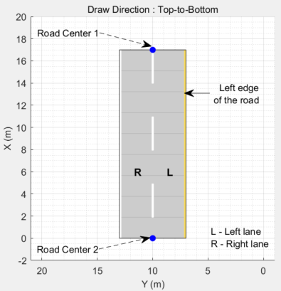
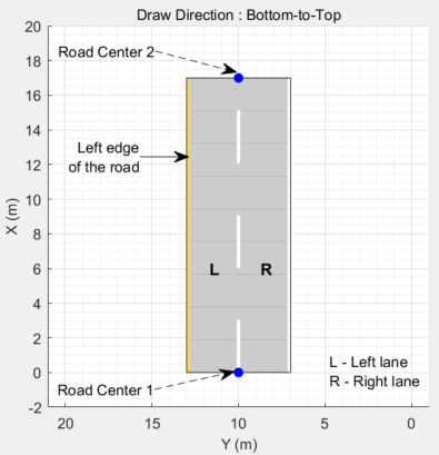
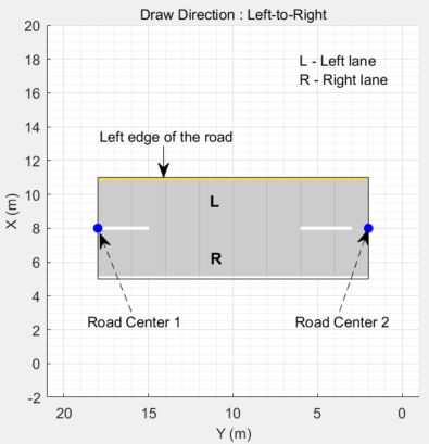
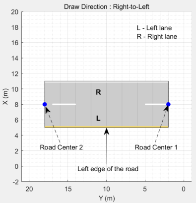
To create a road by using the road function, specify the road centers as a
matrix input. The function creates a directed line that traverses the road centers, starting
from the coordinates in the first row of the matrix and ending at the coordinates in the last
row of the matrix. The coordinates in the first two rows of the matrix specify the
draw direction of the road. These coordinates correspond to the first
two consecutive road centers. The draw direction is the direction in which the roads render in
the scenario plot.
To create a road by using the Driving Scenario Designer app, you can either specify the Road Centers parameter or interactively draw on the Scenario Canvas. For a detailed example, see Create a Driving Scenario. In this case, the draw direction is the direction in which roads render in the Scenario Canvas.
For a road with a top-to-bottom draw direction, the difference between the x-coordinates of the first two consecutive road centers is positive.
For a road with a bottom-to-top draw direction, the difference between the x-coordinates of the first two consecutive road centers is negative.
|
|
|
For a road with a left-to-right draw direction, the difference between the y-coordinates of the first two consecutive road centers is positive.
For a road with a right-to-left draw direction, the difference between the y-coordinates of the first two consecutive road centers is negative.
|
|
|
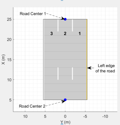
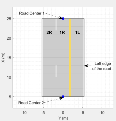
Lanes must be numbered from left to right, with the left edge of the road defined relative to the draw direction of the road. For a one-way road, by default, the left edge of the road is a solid yellow marking which indicates the end of the road in transverse direction (direction perpendicular to draw direction). For a two-way road, by default, both edges are marked with solid white lines.
For example, these diagrams show how the lanes are numbered in a one-way and two-way road with a draw direction from top-to-bottom.
| Numbering Lanes in a One-Way Road | Numbering Lanes in a Two-Way Road |
Specify the number of lanes as a positive integer for a one-way road. If
you set the integer value as 1, 2, 3 denote the first, second, and third lanes of the road, respectively.
| Specify the number of lanes as a two-element vector of positive integer
for a two-way road. If you set the vector as [ 1L denote the only left lane of the road. 1R and 2R denote the first and second right lanes of the road, respectively.
|
The lane specifications apply by the order in which the lanes are numbered.
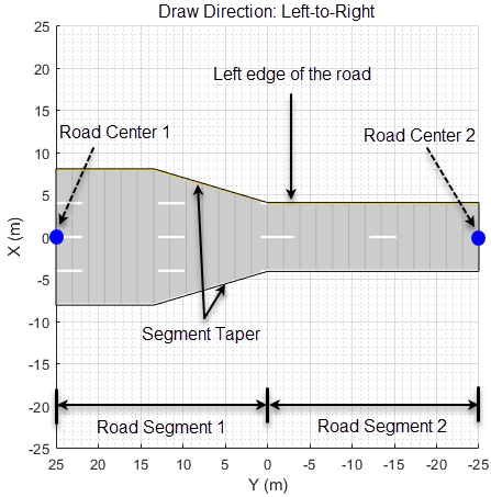
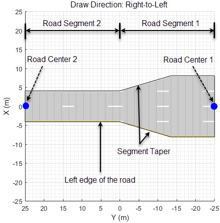
A composite lane specification consists of an array of two or more lane specifications for a single road. Each lane specification defines a road segment, which is a section of the road with independent geometric properties, normalized range, and taper.
Each road segment is a directed segment that moves toward the final road center, with the first segment beginning at the first road center, the second segment starting where the first ends, and so on. The range of each road segment is a normalized distance that specifies a proportion of the total length of the road. When a road segment adds or drops lanes from a previous segment, the preceding segment tapers along a specified distance to accommodate the change in number of lanes.
When you render a road with composite lane specifications, the road segments render in the draw direction of the road. For example, consider a one-way road with two road segments and a default normalized range of 0.5 for each road segment. The first road segment contains four lanes and the second segment contains only two lanes. The first segment tapers from four lanes to two lanes, dropping one lane from each side, as it approaches the halfway point of the road, which is the start point of the second segment. These diagrams show the direction in which the road segments render, and how the taper applies to the road, for both the left-to-right and right-to-left draw directions.
|
|
|
For information on the geometric properties of lanes, see Lane Specifications.
The diagram shows the components and geometric properties of roads, lanes, and lane markings.
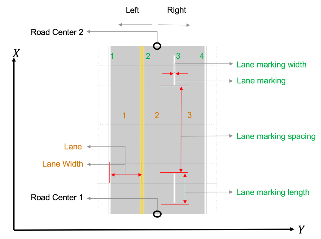
The lane specification object, lanespec, defines the road lanes.
The
NumLanesproperty specifies the number of lanes. You must specify the number of lanes when you create this object.The
Widthproperty specifies the width of each lane.The
Markingproperty contains the specifications of each lane marking in the road.Markingis an array of lane marking objects, with one object per lane. To create these objects, use thelaneMarkingfunction. Lane marking specifications include:Type— Type of lane marking (solid, dashed, and so on)Width— Lane marking widthColor— Lane marking colorStrength— Saturation value for lane marking colorLength— For dashed lanes, the length of each dashed lineSpace— For dashed lanes, the spacing between dashesSegmentRange— For composite lane marking, the normalized length of each marker segment
The
Typeproperty contains the lane type specifications of each lane in the road.Typecan be a homogeneous lane type object or a heterogeneous lane type array.Homogeneous lane type object contains the lane type specifications of all the lanes in the road.
Heterogeneous lane type array contains an array of lane type objects, with one object per lane.
To create these objects, use the
laneTypefunction. Lane type specifications include:Type— Type of lane (driving, border, and so on)Color— Lane colorStrength— Strength of the lane color
Version History
Introduced in R2021a
See Also
Objects
Functions
road|roadNetwork|roadGroup|laneMarking|laneType|vehicle|actor|smoothTrajectory
MATLAB Command
You clicked a link that corresponds to this MATLAB command:
Run the command by entering it in the MATLAB Command Window. Web browsers do not support MATLAB commands.
选择网站
选择网站以获取翻译的可用内容,以及查看当地活动和优惠。根据您的位置,我们建议您选择:。
您也可以从以下列表中选择网站:
如何获得最佳网站性能
选择中国网站(中文或英文)以获得最佳网站性能。其他 MathWorks 国家/地区网站并未针对您所在位置的访问进行优化。
美洲
- América Latina (Español)
- Canada (English)
- United States (English)
欧洲
- Belgium (English)
- Denmark (English)
- Deutschland (Deutsch)
- España (Español)
- Finland (English)
- France (Français)
- Ireland (English)
- Italia (Italiano)
- Luxembourg (English)
- Netherlands (English)
- Norway (English)
- Österreich (Deutsch)
- Portugal (English)
- Sweden (English)
- Switzerland
- United Kingdom (English)
