DC Blocker
Block DC component
Libraries:
DSP System Toolbox /
Signal Operations
Communications Toolbox /
Comm Filters
Communications Toolbox /
RF Impairments Correction
DSP System Toolbox HDL Support /
Signal Operations
Description
The DC Blocker block removes the DC component of the input signal.
This block supports C/C++ code generation and SIMD code generation. For details, see Code Generation.
Examples
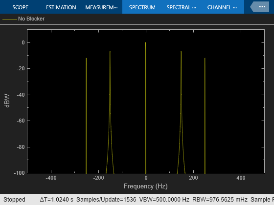
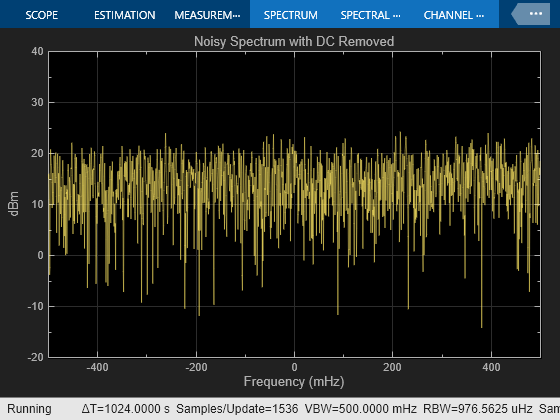
Use DC Blocker to Remove DC Component of Signal
Remove DC component of signal using IIR and Subtract mean estimation algorithms.
DC Blocker with Fixed Point Data
Use DC Blocker block to remove DC offset from fixed-point data.
Ports
Input
Specify the input signal that contains the DC component as a scalar, vector, or a matrix.
If the input is fixed point, it must be a signed integer or a signed fixed point value with a power-of-two slope and zero bias.
Data Types: single | double | int8 | int16 | int32 | fixed point
Complex Number Support: Yes
Output
Output signal with the DC component removed. When the output is fixed-point, it is signed only.
The size, data type, and complexity of the output signal are the same as that of the input signal.
Data Types: single | double | int8 | int16 | int32 | fixed point
Complex Number Support: Yes
Parameters
Specify the algorithm used for estimating the DC offset. Select from the following:
IIRuses a recursive estimate based on a narrow, lowpass elliptic filter. This algorithm typically uses less memory than FIR and is more efficient.FIRuses a nonrecursive, moving-average estimate. This algorithm typically uses more memory than IIR and is less efficient.CICuses a lowpass filter that does not employ any multipliers. If the algorithm isCIC, then fixed-point data must be input to the DC Blocker.Subtract meancomputes the means of the columns of the input matrix and subtracts the means from the input. This method does not retain state between inputs. For example, if the input is[1 2 3 4; 3 4 5 6], then the DC Blocker block inSubtract meanmode outputs[-1 -1 -1 -1; 1 1 1 1].
Specify the normalized filter bandwidth as a real scalar greater than 0 and less than 1.
Dependencies
The DC Blocker uses this parameter only when the
estimation algorithm is set to IIR or
CIC.
Data Types: single | double | int8 | int16 | int32 | int64 | uint8 | uint16 | uint32 | uint64
Specify the filter order of the lowpass IIR elliptic filter as an integer greater than 3.
Dependencies
The DC Blocker uses this parameter only when the
estimation algorithm is set to IIR.
Data Types: single | double | int8 | int16 | int32 | int64 | uint8 | uint16 | uint32 | uint64
Specify, as a positive integer, the number of samples to use when the
estimation algorithm is set to FIR.
Dependencies
The DC Blocker uses this parameter only when the
estimation algorithm is set to FIR.
Data Types: single | double
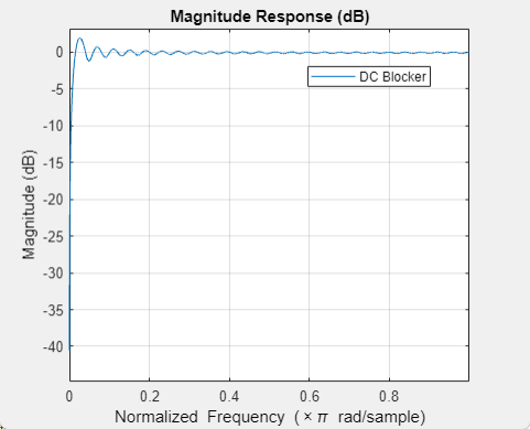
Opens the fvtool and displays the magnitude response
of the DC Blocker. The response is based on the block
parameters. Changes made to these parameters update
fvtool.

To update the magnitude response while fvtool is
running, modify the block parameters and click
Apply.
Specify the type of simulation to run. You can set this parameter to:
Interpreted execution–– Simulate model using the MATLAB® interpreter. This option shortens startup time.Code generation–– Simulate model using generated C code. The first time you run a simulation, Simulink® generates C code for the block. The C code is reused for subsequent simulations as long as the model does not change. This option requires additional startup time but provides faster subsequent simulations.
Block Characteristics
Algorithms
The DC blocker subtracts the DC component from the input signal. You can estimate the DC component by using the IIR, FIR, CIC, or subtract mean algorithm.
Pass the input signal through an IIR lowpass elliptical filter.
The elliptical IIR filter has a passband ripple of 0.1 dB and a stopband attenuation of 60 dB. You specify the normalized bandwidth and the filter order.
Pass the input signal through an FIR filter that uses a nonrecursive moving average from a finite number of past input samples.
The FIR filter coefficients are given as ones(1,Length)/Length, where Length is the number of past input samples for FIR algorithm. The FIR filter structure is a direct form I transposed structure.
Pass the input signal through a CIC filter. Because the CIC filter amplifies the signal, the filter gain is estimated and subtracted from the DC estimate.
The Cascaded Integrator-Comb (CIC) filter consists of two integrator-comb pairs. These pairs help to ensure that the peak of the first sidelobe of the filter response is attenuated by at least 25 dB relative to the peak of the main lobe. The normalized 3 dB bandwidth is used to calculate the differential delay. The delay is used to determine the gain of the CIC filter. The inverse of the filter gain is used as a multiplier, which is applied to the output of the CIC filter. This ensures that the aggregate gain of the DC estimate is 0 dB.
The following equation characterizes the aggregate magnitude response of the filter and the multiplier:
Bnorm is the normalized bandwidth such that 0 < Bnorm < 1.
M is the differential delay in samples.
N is the number of sections, equal to 2.
Set the differential delay, M, to the smallest integer such that |H(ejω)| < 1/√2. Once M is known, the gain of the CIC filter is calculated as MN. Therefore, to precisely compensate for the filter gain, the multiplier is set to (1/M)N.
Compute the mean value of each column of the input signal and subtract the mean from the input. For example, if the input is [1 2 3 4; 3 4 5 6], then a DC Blocker set to this mode outputs [-1 -1 -1 -1; 1 1 1 1].
References
[1] Nezami, M.K. “Performance Assessment of Baseband Algorithms for Direct Conversion Tactical Software Defined Receivers: I/Q Imbalance Correction, Image Rejection, DC Removal, and Channelization.” In MILCOM 2002. Proceedings, 369–76. Anaheim, CA, USA: IEEE, 2002.
Extended Capabilities
The DC Blocker block supports SIMD code generation using Intel AVX2 code
replacement library when the input signal has a data type of
single or double.
The SIMD technology significantly improves the performance of the generated code. For more information, see SIMD Code Generation. To generate SIMD code from this block, see Use Intel AVX2 Code Replacement Library to Generate SIMD Code from Simulink Blocks.
Note
For a DC Blocker optimized for HDL code generation, see High Performance DC Blocker for FPGA (DSP HDL Toolbox). The DSP HDL Toolbox™ block provides an HDL-optimized algorithm with hardware-friendly control signals and simulates the latency of the HDL algorithm in Simulink.
HDL Coder™ provides additional configuration options that affect HDL implementation and synthesized logic.
This block has one default HDL architecture.
| ConstrainedOutputPipeline | Number of registers to place at
the outputs by moving existing delays within your design. Distributed
pipelining does not redistribute these registers. The default is
|
| InputPipeline | Number of input pipeline stages
to insert in the generated code. Distributed pipelining and constrained
output pipelining can move these registers. The default is
|
| OutputPipeline | Number of output pipeline stages
to insert in the generated code. Distributed pipelining and constrained
output pipelining can move these registers. The default is
|
This block supports code generation for complex signals.
Version History
Introduced in R2014aThe default value of the Simulate using parameter is now
Interpreted execution. With this change, the block uses the
MATLAB interpreter for simulation by default.
MATLAB Command
You clicked a link that corresponds to this MATLAB command:
Run the command by entering it in the MATLAB Command Window. Web browsers do not support MATLAB commands.
选择网站
选择网站以获取翻译的可用内容,以及查看当地活动和优惠。根据您的位置,我们建议您选择:。
您也可以从以下列表中选择网站:
如何获得最佳网站性能
选择中国网站(中文或英文)以获得最佳网站性能。其他 MathWorks 国家/地区网站并未针对您所在位置的访问进行优化。
美洲
- América Latina (Español)
- Canada (English)
- United States (English)
欧洲
- Belgium (English)
- Denmark (English)
- Deutschland (Deutsch)
- España (Español)
- Finland (English)
- France (Français)
- Ireland (English)
- Italia (Italiano)
- Luxembourg (English)
- Netherlands (English)
- Norway (English)
- Österreich (Deutsch)
- Portugal (English)
- Sweden (English)
- Switzerland
- United Kingdom (English)

