designDDC
R2026bDescription
H = designDDCdsp.DDC
System object™. The default design uses decimation factors of [25 2 2], a passband ripple of
0.1 dB, a stopband attenuation of 60 dB, and a bandwidth of 90% of the output Nyquist rate.
H = designDDC(Name=Value)designDDC(DecimationFactors=[1365 3],Bandwidth=0.01,StopbandAttenuation=80)
designs a 2-stage DDC with a CIC decimation factor of 1365, a compensating FIR
decimation factor of 3, and 80 dB of stopband attenuation.
Unless you specify the FilterOrders argument, the function uses
minimum order design. Once you specify FilterOrders, the function
uses the specified order design.
Examples
Design a digital downconverter using default specifications. Display the resolved design parameters and visualize the filter response.
Design a 3-stage DDC with default specifications and display the resolved design parameters.
H = designDDC(Verbose=true)
designDDC(DecimationFactors=[25 2 2], Bandwidth=0.018000000000000002, PassbandRipple=0.1, StopbandAttenuation=60, InputSampleRate="normalized")
H =
  dsp.DDC with properties:

    NormalizedFrequency: true
             Oscillator: "Sine wave"
        CenterFrequency: 0
                 Filter: [1×1 dsp.FilterCascade]
          MixerDataType: "Same as input"
Visualize the frequency response of the filter cascade.
filterAnalyzer(H.Filter)
Design a 2-stage dsp.DDC object with custom specifications. Use the resulting object to downconvert a signal from 50 kHz to baseband.
Design a 2-stage DDC with a total decimation factor of 4095, operating at a 1 MHz input sample rate.
Fs = 1e6;
M = [1365 3];
H = designDDC(DecimationFactors=M, ...
    InputSampleRate=Fs, ...
    StopbandAttenuation=80, ...
    Verbose=true);
designDDC(DecimationFactors=[1365 3], Bandwidth=219.7802197802198, PassbandRipple=0.1, StopbandAttenuation=80, InputSampleRate=1000000)
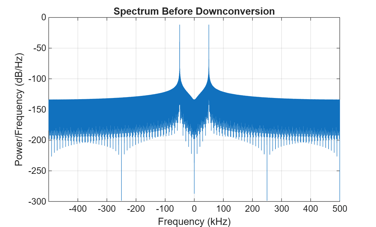
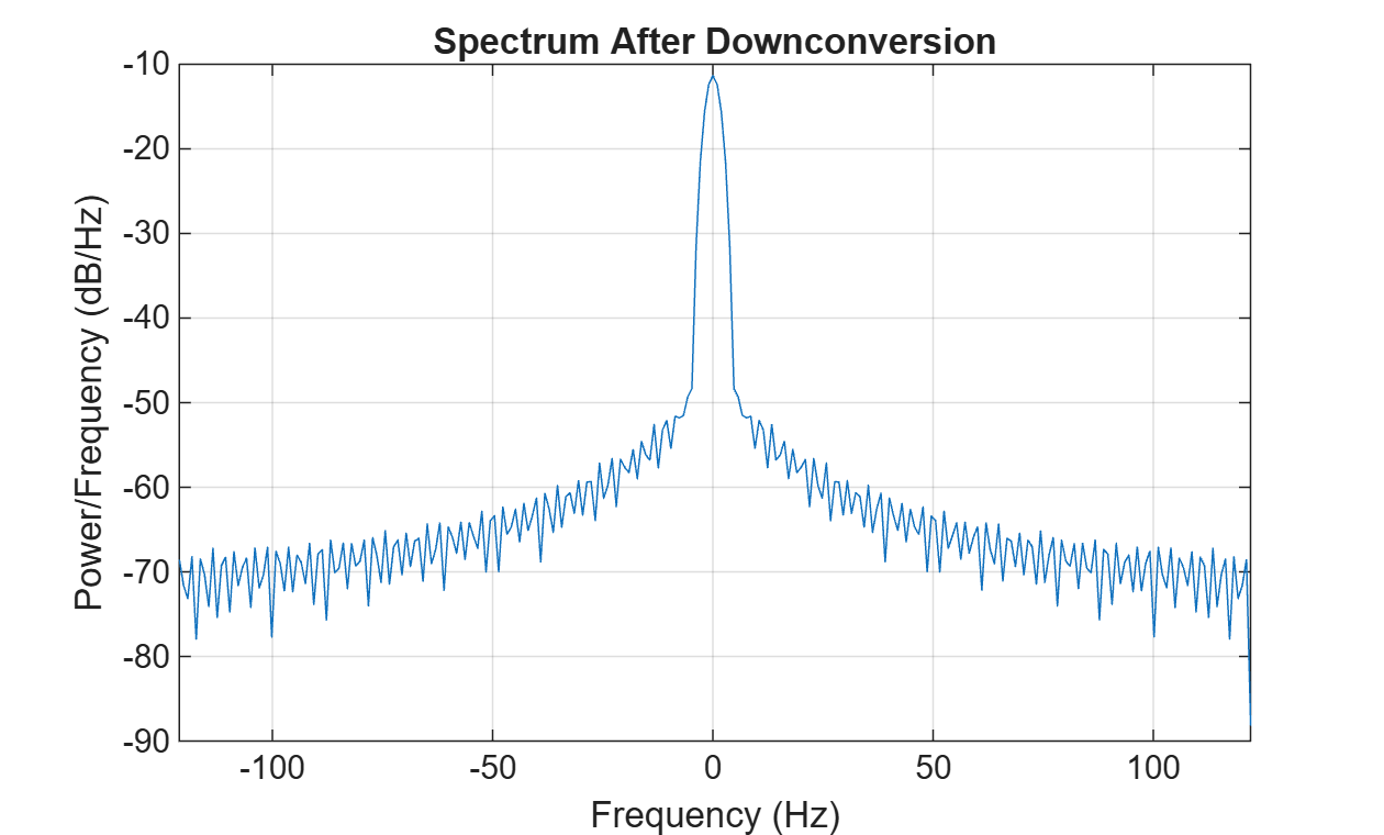
Set the center frequency to 50 kHz. Generate a test signal containing a tone at 50 kHz and downconvert it to baseband.
H.CenterFrequency = 50e3;
t = (0:4095*1000-1)'/Fs;
x = cos(2*pi*50e3*t);
y = H(x);
Visualize the spectrum before and after downconversion.
FsOut = Fs/prod(M);
window = hamming(floor(length(x)/10));
figure
pwelch(x,window,[],[],Fs,"centered")
title("Spectrum Before Downconversion")
window = hamming(floor(length(y)/10));
figure
pwelch(y,window,[],[],FsOut,"centered")
title("Spectrum After Downconversion")
Design a 3-stage dsp.DDC object at a specific input sample rate and inspect the filter cascade.
Design a 3-stage DDC at 1 MHz with decimation factors [631 7 2].
M = [631 7 2];
H = designDDC(DecimationFactors=M, InputSampleRate=1e6, Verbose=true);
designDDC(DecimationFactors=[631 7 2], Bandwidth=101.87910346388952, PassbandRipple=0.1, StopbandAttenuation=60, InputSampleRate=1000000)
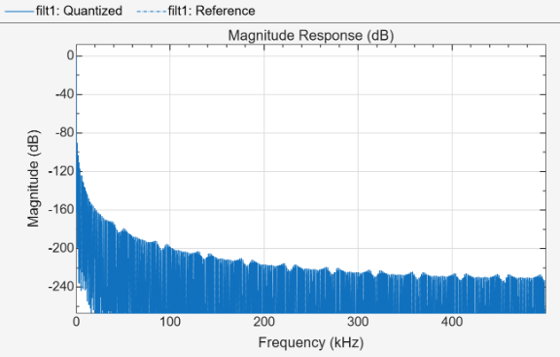
View the filter cascade information and frequency response.
info(H)
ans =
    'Digital Down Converter
     ----------------------------
     Input sample rate                    : 1 MHz
     Oscillator type                      : Sine wave
     Oscillator center frequency          : 0 Hz

     ----------------------------------------------------
     Filter type           : dsp.FilterCascade
     Rate conversion ratio : 1:8834

     Discrete-Time Filter Cascade
     ----------------------------
     Number of stages: 4
     Stage cloning: enabled
     ----------------------------
     Stage1: dsp.CICDecimator
     -------
     Discrete-Time FIR Multirate Filter (real)
     -----------------------------------------
     Filter Structure    : Cascaded Integrator-Comb Decimator
     Decimation Factor   : 631
     Differential Delay  : 1
     Number of Sections  : 3
     Stable              : Yes
     Linear Phase        : Yes (Type 1)

     Stage2: double
     -------
     Stage3: dsp.FIRDecimator
     -------
     Discrete-Time FIR Multirate Filter (real)
     -----------------------------------------
     Filter Structure   : Direct-Form FIR Polyphase Decimator
     Decimation Factor  : 7
     Polyphase Length   : 7
     Filter Length      : 43
     Stable             : Yes
     Linear Phase       : Yes (Type 1)

     Stage4: dsp.FIRDecimator
     -------
     Discrete-Time FIR Multirate Filter (real)
     -----------------------------------------
     Filter Structure   : Direct-Form FIR Polyphase Decimator
     Decimation Factor  : 2
     Polyphase Length   : 38
     Filter Length      : 75
     Stable             : Yes
     Linear Phase       : Yes (Type 1)


     '
filterAnalyzer(H.Filter)
Design a dsp.DDC object by specifying the filter orders for each stage instead of using minimum order design.
Design a 2-stage DDC with a CIC section count of 7 and a compensator FIR order of 50.
H = designDDC(DecimationFactors=[120 7], FilterOrders=[7 50], Verbose=true);
designDDC(DecimationFactors=[120 7], Bandwidth=0.002142857142857143, FilterOrders=[7 50], InputSampleRate="normalized")
Display the filter cascade information.
info(H)
ans =
    'Digital Down Converter
     ----------------------------
     Input sample rate                    : normalized
     Oscillator type                      : Sine wave
     Oscillator center frequency          : 0 (normalized)

     ----------------------------------------------------
     Filter type           : dsp.FilterCascade
     Rate conversion ratio : 1:840

     Discrete-Time Filter Cascade
     ----------------------------
     Number of stages: 3
     Stage cloning: enabled
     ----------------------------
     Stage1: dsp.CICDecimator
     -------
     Discrete-Time FIR Multirate Filter (real)
     -----------------------------------------
     Filter Structure    : Cascaded Integrator-Comb Decimator
     Decimation Factor   : 120
     Differential Delay  : 1
     Number of Sections  : 7
     Stable              : Yes
     Linear Phase        : Yes (Type 2)

     Stage2: double
     -------
     Stage3: dsp.FIRDecimator
     -------
     Discrete-Time FIR Multirate Filter (real)
     -----------------------------------------
     Filter Structure   : Direct-Form FIR Polyphase Decimator
     Decimation Factor  : 7
     Polyphase Length   : 8
     Filter Length      : 51
     Stable             : Yes
     Linear Phase       : Yes (Type 1)


     '
Name-Value Arguments
Output Arguments
Algorithms
The designDDC function designs a multistage decimation filter
cascade equivalent to a single-stage lowpass FIR filter followed by a rate-change
element. The cascade consists of:
CIC Decimator — Performs the bulk of the decimation at a low computational cost.
Gain Normalization — A scalar that compensates for the CIC gain.
CIC Compensator FIR Decimator — Compensates for the CIC passband droop and provides additional decimation.
Auxiliary FIR Decimator (3-stage only) — Provides additional filtering and decimation by a factor of 1 or 2.
The following diagram shows the 3-stage filter cascade structure. For a 2-stage design, the auxiliary FIR decimator is not present.
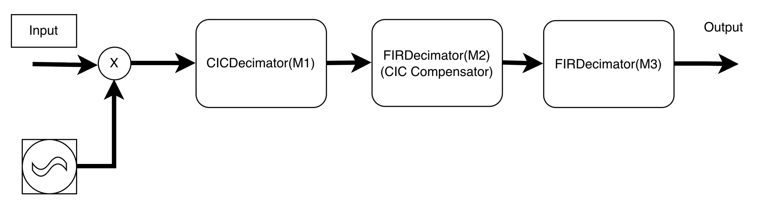
The CIC decimator performs the bulk of the rate change with decimation factor M1. The
CIC compensator FIR decimator corrects the passband droop introduced by the CIC stage and
decimates by a factor of M2. The auxiliary FIR decimator, present only in 3-stage designs,
provides additional filtering and decimates by a factor of M3 (1 or 2). The elements of
the DecimationFactors argument correspond to [M1 M2] for a 2-stage
design or [M1 M2 M3] for a 3-stage design.
Version History
Introduced in R2026b

