NFC Digital Downconverter Using dsp.DDC
R2026bNear-field communication (NFC) systems operate at data rates of 424, 212, or 106 kS/s. However, ADCs used in NFC test equipment typically sample at rates of 100 MS/s or higher. To translate a narrowband NFC signal carried at 13.56 MHz from the high ADC sample rate to the baseband subcarrier rate, use a digital downconverter (DDC). For an overview of NFC signaling, modulation schemes, and protocol considerations, see NFC Digital Downconverter (DSP HDL Toolbox).
This example builds a DDC that decimates a 100 MS/s input signal to a near-baseband rate of 636 kS/s, for an overall rate-change factor of approximately 157. Rather than performing the entire conversion in a single stage, the design strategically distributes the rate change across a cascade of CIC, FIR, and Farrow filters. Each stage is selected to balance computational efficiency, filtering performance, and implementation complexity. The 636 kS/s output rate is 1.5× oversampled relative to the 424 kHz NFC data rate, providing margin for downstream symbol-timing recovery.
The example assembles the complete cascade into a dsp.DDC object, which pairs a custom filter with an NCO mixer for frequency translation.
Design Parameters
Define the key rates and spectral constraints for the DDC. Fpass is the one-sided signal bandwidth (the NFC modulation occupies approximately ±200 kHz around the carrier). Fstop defines the anti-alias protection edge used by intermediate stages — filters early in the chain must be flat out to Fstop so that the final channel-selection filter can shape the passband precisely at Fpass.
FsIn  = 100e6;       % ADC sample rate (Hz)
Fc    = 13.56e6;     % NFC carrier frequency (Hz)
FsOut = 424e3;       % NFC data rate (Hz)
Fpass = 200e3;       % Passband frequency: NFC signal bandwidth
Fstop = 480e3;       % Stopband frequency
Ap    = 0.1;         % Passband ripple (dB)
Ast   = 60;          % Stopband attenuation (dB)
Custom DDC Filter Cascade
The DDC filter cascade decimates from 100 MS/s to 636 kS/s in five stages, not including a scaling stage:

Assign each stage a specific role to balance computational cost and spectral performance:
Use a CIC filter to perform the bulk decimation at the highest sample rate.
Apply a compensation filter to correct CIC passband droop.
Use a Farrow rate converter to implement the non-integer rate conversion. The Farrow rate change is kept near 1.23:1 to minimize aliasing from the polynomial interpolation.
Apply a halfband filter for efficient decimation by a factor of 2.
Use a channel-selection FIR filter to shape the final bandwidth and stopband rejection.
Stage 1: CIC Decimation by 16
The first stage is a fourth-order dsp.CICDecimator object with a decimation factor of 16. It performs the bulk of the rate reduction using a multiplier-free CIC structure, which minimizes computational cost. The filter reduces the sample rate from 100 MS/s to 6.25 MHz, significantly reducing the remaining conversion burden on the subsequent FIR and Farrow stages.
cicDecim = dsp.CICDecimator( ...
    DecimationFactor  = 16, ...
    NumSections       = 4, ...
    DifferentialDelay = 1, ...
    InputSampleRate   = FsIn);
The CIC filter introduces a gain is which must be normalized before subsequent stages.
cicGain = gain(cicDecim); % (16*1)^4Stage 2: CIC Droop Compensation and Decimation by a factor 2
The simplicity of the CIC structure comes with a tradeoff: the passband is not flat. Instead, the CIC filter exhibits a sinc-shaped frequency response whose gain gradually decreases with frequency. Use dsp.CICCompensationDecimator to design an inverse-sinc FIR filter that compensates for the passband droop while performing an additional half-band decimation by a factor of 2. After this stage, the output sample rate is.
FsCompOut = FsIn / 32;      % 3.125 MHz: output rate after CIC+comp
droopComp = dsp.CICCompensationDecimator(cicDecim, 2, ...
    SampleRate          = FsIn/16, ...
    PassbandFrequency   = Fstop, ...
    StopbandFrequency   = FsCompOut/2, ...
    PassbandRipple      = 0.01, ...
    StopbandAttenuation = Ast);
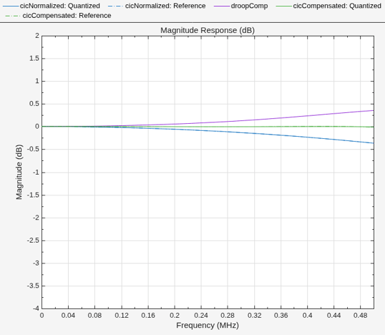
Compensated CIC Response
Verify that the droop compensator flattens the CIC passband out to 480 kHz using the filterAnalyzer command. The compensation extends beyond the 200 kHz signal bandwidth so that downstream channel-selection filtering has a flat input to work with. Plot the normalized CIC response, the compensation filter response, and their combined response to show how the inverse-sinc correction restores passband flatness to within ±0.01 dB.
cicNormalized = cascade(cicDecim,1/cicGain,InputSampleRate="auto");
cicCompensated = cascade(cicNormalized, droopComp,InputSampleRate="auto");
fa = filterAnalyzer(cicNormalized, droopComp, cicCompensated);
zoom(fa, "xy", [0 500e3 -4 2])
Stage 3: Farrow (Fractional) Rate Converter
The target output rate of 636 kS/s is not an integer submultiple of 3.125 MHz. Use a dsp.FarrowRateConverter object to implement the required fractional rate change. A Farrow structure performs arbitrary rational sample-rate conversion using a polynomial interpolation filter whose coefficients are computed dynamically.
This stage converts the sample rate from 3.125 MHz to MHz. The rate change of approximately 1.23:1 is deliberately kept small to minimize aliasing from the polynomial interpolation. The output rate is chosen so that subsequent integer decimation by 4 (two stages of ÷2) produces the 636 kS/s target.
FsFarrowOut = 6 * FsOut;      % 2.544 MHz
farrowStage = dsp.FarrowRateConverter(FsCompOut, FsFarrowOut);
Verify that the Farrow filter has an approximately flat response over the bandwidth of interest.
fa = filterAnalyzer(farrowStage);
zoom(fa, "x", [0 500e3])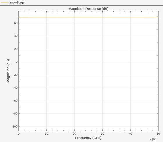
Stage 4: Halfband Decimator
Use the designHalfbandFIR function to design a halfband Nyquist filter. This design is an efficient choice for decimation by 2 because the Nyquist constraint forces every other coefficient to zero, reducing the number of required multiplications by nearly half. The transition band is centered at , so the design task reduces to selecting an appropriate stopband attenuation and transition width.
The output sample rate after this stage is MHz.
FsHalfbandIn = FsFarrowOut;              % 2.544 MHz
hbFsOut      = FsHalfbandIn / 2;         % 1.272 MHz
hbTW         = hbFsOut - 2*Fstop;        % Halfband TW = output rate minus guard bands on both sides
hbDecim = designHalfbandFIR( ...
    StopbandAttenuation = Ast, ...
    InputSampleRate     = FsHalfbandIn, ...
    TransitionWidth     = hbTW, ...
    Structure           = "decim", ...
    SystemObject        = true);
Verify that the halfband filter passband covers the signal bandwidth with adequate margin.
fa = filterAnalyzer(hbDecim);
zoom(fa, "x", [0 750e3])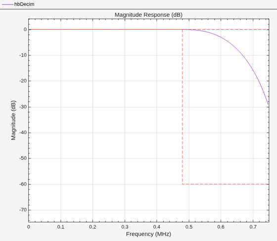
Stage 5: Final Decimation Channel Selection Filter
The final stage performs the remaining decimation by 2 to the target output rate of 636 kS/s, and shapes the channel bandwidth. Because it operates at the lowest sample rate in the cascade, this stage can enforce the most stringent filtering requirements while keeping the implementation efficient. Use the designMultirateFIR function with 0.1 dB passband ripple and 60 dB stopband attenuation to design this filter. Set OverlapTransition=false to ensure that the transition band does not extend beyond the nominal decimation cutoff frequency, preventing aliasing after decimation.
The designMultirateFIR function places the cutoff at the output Nyquist frequency: kHz. The transition width controls how far inward from this cutoff the passband edge sits. A transition width of 118 kHz yields a passband edge of 200 kHz, matching the NFC signal bandwidth.
FsFinalIn     = hbFsOut;                  % 1.272 MHz
FsNyquistOut  = FsFinalIn / 4;            % 318 kHz (output Nyquist)
TW            = FsNyquistOut - Fpass;     % 118 kHz transition width
finalFIR = designMultirateFIR( ...
    DecimationFactor    = 2, ...
    TransitionWidth     = TW, ...
    DesignMethod        = "equiripple", ...
    PassbandRipple      = Ap, ...
    StopbandAttenuation = Ast, ...
    OverlapTransition   = false, ...
    InputSampleRate     = FsFinalIn, ...
    SystemObject        = true);
Confirm that the channel selection filter passband edge at 200 kHz and cutoff at 318 kHz remain below the output Nyquist frequency.
fa = filterAnalyzer(finalFIR);
zoom(fa, "x", [0 450e3])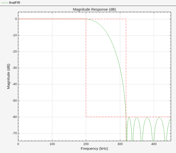
The Full Filter Pipeline
Use cascade to assemble the stages into a single multirate filter cascade. Apply CIC gain normalization immediately after the CIC stage and before the compensation filter. This normalization prevents excessive signal growth that could otherwise cause overflow or reduce precision in downstream fixed-point stages.
F_ddc = cascade(cicDecim, 1/cicGain, droopComp, farrowStage, ...
                   hbDecim, finalFIR, InputSampleRate = "auto");
Composite Multirate Response
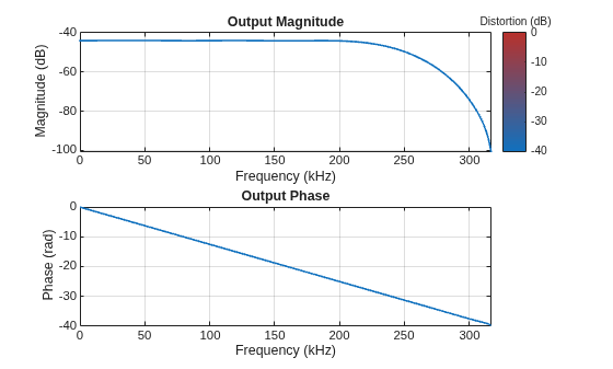
Use freqzmr to compute the end-to-end magnitude response of the complete multirate cascade while accounting for the sample-rate changes at each stage. The passband gain of approximately −44 dB does not indicate signal loss. Instead, it reflects the discrete-time amplitude scaling associated with the overall decimation factor of ~157: dB.
freqzmr(F_ddc)
Simulation Using the dsp.DDC Object
Pass the multistage filter cascade to a dsp.DDC object. The DDC combines the custom decimation filter with an NCO that generates the 13.56 MHz mixing signal for frequency translation to baseband.
H_ddc = dsp.DDC( ...
    InputSampleRate            = FsIn, ...
    CenterFrequency            = Fc, ...
    Oscillator                 = "NCO", ...
    NumAccumulatorBits         = 16, ...
    NumQuantizedAccumulatorBits = 12, ...
    Dither                     = true, ...
    NumDitherBits              = 4, ...
    Filter                     = F_ddc)
H_ddc =
  dsp.DDC with properties:

            NormalizedFrequency: false
                InputSampleRate: 100000000
                     Oscillator: "NCO"
                CenterFrequency: 13560000
                         Filter: [1×1 dsp.FilterCascade]
             NumAccumulatorBits: 16
    NumQuantizedAccumulatorBits: 12
                         Dither: true
                  NumDitherBits: 4
                  MixerDataType: "Same as input"
Verification: Process a Narrowband NFC Signal
Generate a bandlimited noise signal centered at 13.56 MHz and pass it through the DDC to verify end-to-end operation. Quantize the input to 14-bit signed fixed point to simulate a typical NFC receiver ADC.
FrameSize = 100000;
Nframes   = 10;
ADC_WordLength = 14;
Signal Generation
Generate white noise using dsp.ColoredNoise, then filter it through a lowpass IIR filter to produce narrowband complex baseband signal with an approximate bandwidth of 200 kHz. Modulate this baseband signal to the carrier frequency using a complex exponential, and take the real part to produce a real-valued bandpass signal centered at MHz. This approach emulates the output of a digital upconverter (DUC) without explicitly implementing a DUC.
noiseGen = dsp.ColoredNoise( ...
    Color           = "white", ...
    SamplesPerFrame = FrameSize, ...
    NumChannels     = 2);

bbShaper = designfilt('lowpassiir', ...
    PassbandFrequency   = 200e3, ...
    StopbandFrequency   = 300e3, ...
    PassbandRipple      = 1, ...
    StopbandAttenuation = 60, ...
    SampleRate          = FsIn, ...
    SystemObject        = true);

carrier = dsp.SineWave( ...
    Frequency     = Fc, ...
    ComplexOutput = true, ...
    SampleRate    = FsIn, ...
    SamplesPerFrame = FrameSize);
Run the DDC
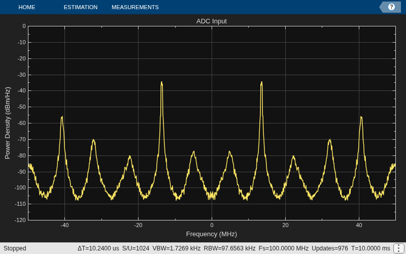
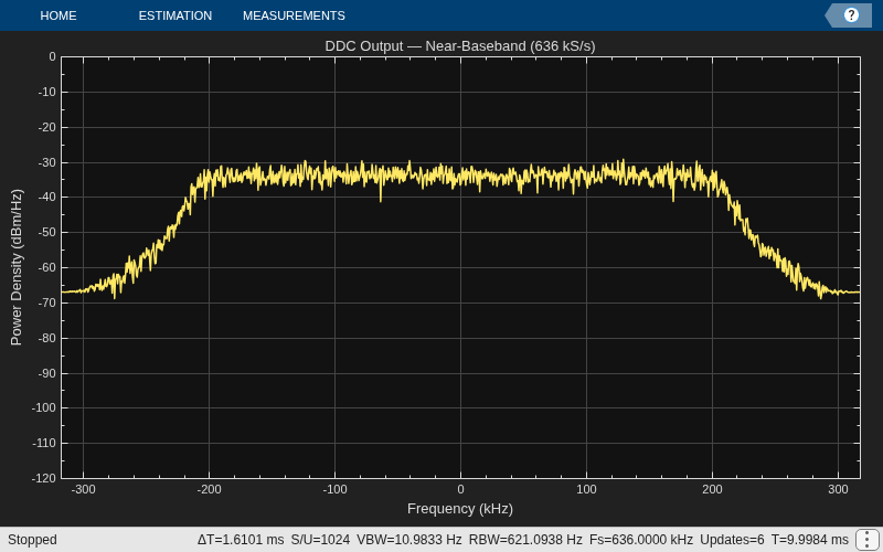
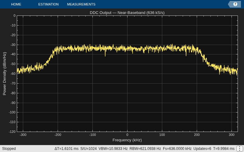
Use two spectrumAnalyzer objects to compare the signal spectrum before and after downconversion. The input analyzer displays the full ADC bandwidth, while the output analyzer displays the downconverted baseband signal at the 636 kS/s output rate.
After downconversion, the signal energy should be concentrated at baseband within ±200 kHz. The channel-selection filter suppresses aliasing and out-of-band components by at least 60 dB.
saIn = spectrumAnalyzer( ...
    SampleRate      = FsIn, ...
    SpectrumType    = "power-density", ...
    Title           = "ADC Input", ...
    YLimits         = [-120 0]);

FsDDCOut = FsFarrowOut / 4;  % 636 kHz (output of halfband + final ÷2)
saOut = spectrumAnalyzer( ...
    SampleRate      = FsDDCOut, ...
    SpectrumType    = "power-density", ...
    Title           = "DDC Output — Near-Baseband (636 kS/s)", ...
    YLimits         = [-120 0], ...
    FrequencySpan   = "start-and-stop-frequencies", ...
    StartFrequency  = -FsDDCOut/2, ...
    StopFrequency   = FsDDCOut/2);

rng(42)

awgn_complex = @() noiseGen()*[1; 1j];

for k = 1:Nframes
    noiseBB = bbShaper(awgn_complex());
    noiseBB = noiseBB / rms(noiseBB);
    xIF = real(noiseBB .* carrier());
    xIF = fi(xIF, true, ADC_WordLength, ADC_WordLength-1);

    saIn(double(xIF))
    y = H_ddc(xIF);
    saOut(double(y))
end
release(saIn)
release(saOut)
release(H_ddc)
Shortcut: designDDC for the CIC Portion
The custom cascade described above provides full control over every design parameter. When a compensated CIC front end is sufficient, use designDDC to generate the CIC and compensation-filter stages automatically in a single call.
The function selects the CIC order and compensation-filter length required to meet the specified passband and stopband requirements.
H_auto = designDDC( ...
    DecimationFactors   = [16 2], ...
    InputSampleRate     = FsIn, ...
    Bandwidth           = 2*Fstop, ...
    StopbandFrequency   = FsCompOut/2, ...
    StopbandAttenuation = Ast, ...
    PassbandRipple      = 0.01, ...
    Verbose             = true);
designDDC(DecimationFactors=[16 2], Bandwidth=960000, StopbandFrequency=1562500, PassbandRipple=0.01, StopbandAttenuation=60, InputSampleRate=100000000)
Note the two designs are identical
fa = filterAnalyzer(H_auto.Filter, cascade(cicDecim, 1/cicGain, droopComp, InputSampleRate=FsIn));
zoom(fa, "xy", [0 2e6 -120 2])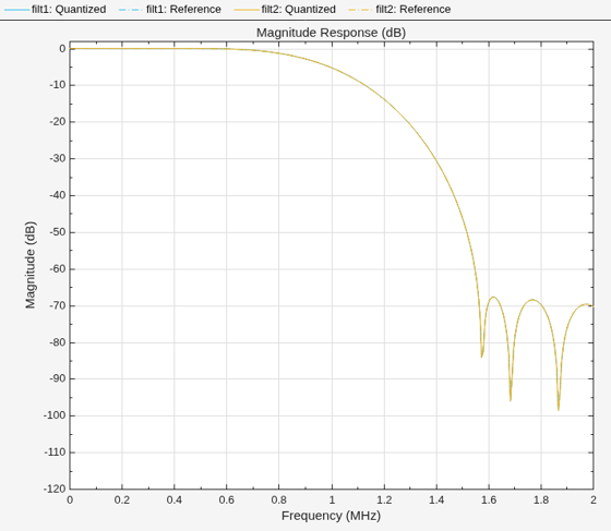
Alternative: designRateConverter for Stages 4–5
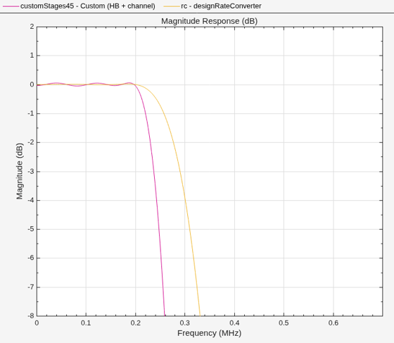
The custom design uses a halfband filter for broad anti-alias protection (passband to 480 kHz), followed by a channel-selection FIR that shapes the precise signal bandwidth (passband to 200 kHz). An alternative approach uses designRateConverter to design a cost-optimized single- or multistage decimator that targets the output Nyquist frequency directly.
Choose designRateConverter when downstream processing, such as matched filtering or symbol-timing recovery, performs its own bandwidth limiting. This approach removes the explicit channel-selection stage and can reduce implementation cost. Choose the custom two-stage design when the DDC must deliver a precisely shaped channel at its output.
rc = designRateConverter( ...
    DecimationFactor    = 4, ...
    InputSampleRate     = FsFarrowOut, ...
    Bandwidth           = Fpass, ...
    StopbandAttenuation = Ast);
Compare the composite response of the two approaches. The custom design has a narrower passband (200 kHz) with sharp channel selection, while designRateConverter has a wider passband extending closer to the output Nyquist (318 kHz) with a more gradual rolloff.
customStages45 = cascade(hbDecim, finalFIR, InputSampleRate="auto");
fa = filterAnalyzer(customStages45, rc, ...
    Legend=["Custom (HB + channel)", "designRateConverter"]);
zoom(fa, "xy", [0 700e3 -8 2])
Compare the computational cost. The designRateConverter approach typically requires fewer multiplications because it does not enforce the tight channel-selection bandwidth of the custom design.
costCustom = cost(customStages45)
costCustom = struct with fields:
                  NumCoefficients: 47
                        NumStates: 56
    MultiplicationsPerInputSample: 15.5000
          AdditionsPerInputSample: 14.7500
costAuto = cost(rc)
costAuto = struct with fields:
                  NumCoefficients: 29
                        NumStates: 36
    MultiplicationsPerInputSample: 7.2500
          AdditionsPerInputSample: 7
H_auto.Filter = cascade(H_auto.Filter, farrowStage, rc, InputSampleRate="auto");
H_auto.CenterFrequency = Fc;
H_auto.Oscillator = "NCO";
H_auto
H_auto =
  dsp.DDC with properties:

            NormalizedFrequency: false
                InputSampleRate: 100000000
                     Oscillator: "NCO"
                CenterFrequency: 13560000
                         Filter: [1×1 dsp.FilterCascade]
             NumAccumulatorBits: 16
    NumQuantizedAccumulatorBits: 12
                         Dither: true
                  NumDitherBits: 4
                  MixerDataType: "Same as input"
Verify the Automated Design
Process the same narrowband NFC signal through H_auto and compare the output spectrum with that of the custom design. Verify that both implementations produce equivalent baseband bandwidth, passband shape, and out-of-band rejection at the 636 kS/s output rate.
rng(42)
reset(noiseGen)
reset(bbShaper)
reset(carrier)

for k = 1:Nframes
    noiseBB = bbShaper(awgn_complex());
    noiseBB = noiseBB / rms(noiseBB);
    xIF = real(noiseBB .* carrier());
    xIF = fi(xIF, true, ADC_WordLength, ADC_WordLength-1);
    yAuto = H_auto(xIF);
    saOut(double(yAuto))
end
release(saOut)
release(H_auto)

