dsp.VariableFIRDecimator
Description
The dsp.VariableFIRDecimator object performs an efficient polyphase FIR
decimation with a tunable decimation factor. You can update the decimation factor and the
filter coefficients while the simulation is running. To control the decimation, you can
specify the decimation factor or the output frame length.
When you specify the decimation factor, if the input frame length changes (variable-size signal) during simulation, the output frame length also changes in order to keep the decimation factor constant. When you specify the output frame length instead of the decimation factor, and if the input frame length changes (variable-size signal) during simulation, the decimation factor also changes in order to keep the output frame length constant.
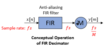
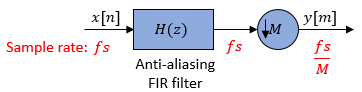
Conceptually, the FIR decimator (as shown in the schematic) consists of an anti-aliasing
FIR filter followed by a downsampler. To design an FIR anti-aliasing filter, use the designMultirateFIR function.
The FIR filter filters the data in each channel of the input using a direct-form FIR filter. The downsampler that follows downsamples each channel of filtered data by taking every M-th sample and discarding the M – 1 samples that follow. M is the value of the decimation factor. The resulting discrete-time signal has a sample rate that is 1/M times the original sample rate.
Note that the actual object algorithm implements a direct-form FIR polyphase structure, an efficient equivalent of the combined system depicted in the diagram. For more details, see Algorithms.
This object supports C and C++ code generation.
To implement the variable FIR decimator:
Create the
dsp.VariableFIRDecimatorobject and set its properties.Call the object with arguments, as if it were a function.
To learn more about how System objects work, see What Are System Objects?
Creation
Syntax
Description
varFIRDecim = dsp.VariableFIRDecimatordesignMultirateFIR(1,24).
varFIRDecim = dsp.VariableFIRDecimator(Mmax)MaxDecimationFactor property to
Mmax.
varFIRDecim = dsp.VariableFIRDecimator(Mmax,M)DecimationFactor property to M. The
object designs the FIR filter using
designMultirateFIR(1,M). The designed filter
corresponds to a lowpass filter with a cutoff at π/M in radial
frequency units.
varFIRDecim = dsp.VariableFIRDecimator(PropertyName=Value)varFIRDecim =
dsp.VariableFIRDecimator(Specification="Output frame length") creates a
variable FIR decimator object with an output frame length of 48.
Properties
Usage
Description
Input Arguments
Output Arguments
Object Functions
To use an object function, specify the
System object™ as the first input argument. For
example, to release system resources of a System object named obj, use
this syntax:
release(obj)
Examples
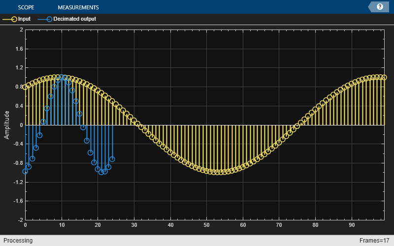
Decimate a sinusoidal signal whose frame length varies during simulation. The dsp.VariableFIRDecimator object determines the frame length of the decimated output based on the value of the Specification property
Specify Decimation Factor
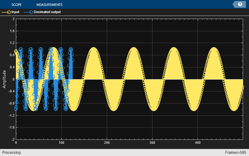
The two input sinusoidal signals have frame lengths of 1000 and 500, respectively. Initialize the dsp.VariableFIRDecimator object with a decimation factor of 4. Initialize the array plot to visualize the input and decimated output signals.
Fs = 44100;
sw1 = dsp.SineWave(SampleRate=Fs,...
    SamplesPerFrame=1000,Frequency=500);
sw2 = dsp.SineWave(SampleRate=Fs,...
    SamplesPerFrame=500,Frequency=500);
varDecim = dsp.VariableFIRDecimator(DecimationFactor=4)
varDecim =
  dsp.VariableFIRDecimator with properties:

          Specification: 'Decimation factor'
    MaxDecimationFactor: 24
       DecimationFactor: 4
        NumeratorSource: 'Auto'
ap = dsp.ArrayPlot(YLimits=[-2 2],...
    ChannelNames=["Input","Decimated output"]);
Stream in data. Change the frame length of the input signal during simulation. In this mode, the object maintains the decimation factor and varies the output frame length so that output frame length equals the ratio of input frame length and decimation factor. Visualize the input and decimated output signals in an array plot.
for i = 1:100000
    if i < 50000
        input = sw1();
    else
        input = sw2();
    end
    output = varDecim(input);
    ap(input,output)
end
release(varDecim)
Specify Output Frame Length
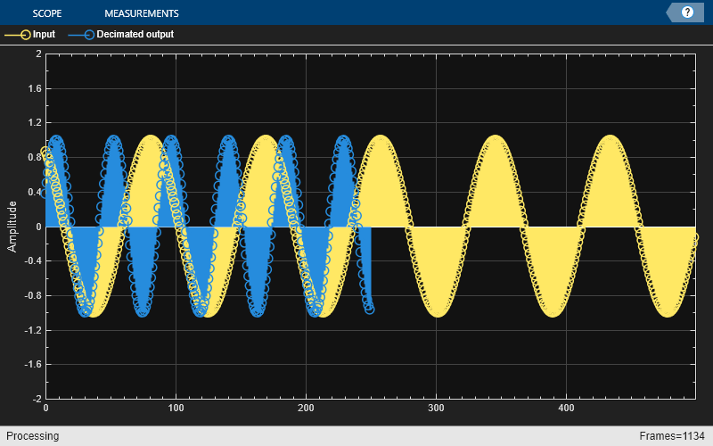
Change the Specification property to 'Output frame length'. Specify the output frame length to 250. Stream in the two input sinusoidal signals again. During simulation, when the input frame length varies, the output frame length remains constant. The object varies the decimation factor in order to maintain the frame length of the output signal. The output frame length equals the ratio of input frame length and decimation factor.
varDecim.Specification = "Output frame length";
varDecim.OutputFrameLength = 250;
for i = 1:100000
    if i < 50000
        input = sw1();
    else
        input = sw2();
    end
    output = varDecim(input);
    ap(input,output)
end
Decimate a sinusoidal signal by varying the decimation factor during simulation.
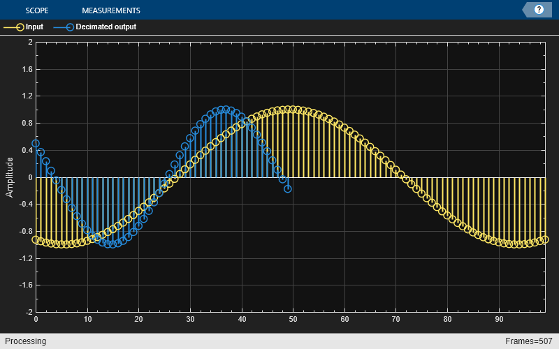
The input is a sinusoidal signal with a frequency of 500 Hz, sample time of 1/44100 s, and contains 100 samples per frame. Initialize the dsp.VariableFIRDecimator object with a maximum decimation factor of 24 and a decimation factor of 8. Initialize the array plot to view the input and decimated output signals.
Fs = 44100;
sw = dsp.SineWave(SampleRate=Fs,SamplesPerFrame=100,Frequency=500);
varDecim = dsp.VariableFIRDecimator(24,8);
ap = dsp.ArrayPlot(YLimits=[-2 2],...
    ChannelNames=["Input","Decimated output"]);
Stream in the data. During simulation, change the decimation factor to 2. The span of the decimated output updates in the array plot display. You can change the decimation factor to any value that is an integer factor of the maximum decimation factor of 24.
for i = 1:1500
    input = sw();
    output = varDecim(input);
    ap(input,output);
    if i==500
        varDecim.DecimationFactor = 2;
    end
end
Specify the filter coefficients as an input to the dsp.VariableFIRDecimator object. You can vary these coefficients during simulation and see the impact on the decimator output.
The input is a sinusoidal signal with a frequency of 500 Hz, sample time of 1/44100 s, and contains 100 samples per frame. Initialize the dsp.VariableFIRDecimator object with a decimation factor of 4 and with the NumeratorSource property set to 'Input port'. Initialize the array plot to view the input and decimator output signals.
Fs = 44100;
sw = dsp.SineWave(SampleRate=Fs,SamplesPerFrame=100,Frequency=500);
varDecim = dsp.VariableFIRDecimator(DecimationFactor=4,...
    NumeratorSource="Input port");
ap = dsp.ArrayPlot(YLimits=[-2 2],...
    ChannelNames=["Input","Decimated output"]);
Stream in the input signal. Specify the filter coefficients as an input to the object algorithm. Initially, the object algorithm generates the filter coefficients using designMultirateFIR(1,24). This function generates an effective anti-aliasing lowpass filter with a normalized cutoff frequency no greater than 1/24.
During simulation, change the filter coefficients to [fir1(24*16-1,1/24) zeros(1,192)]. The fir1 function generates the coefficients of a lowpass filter that has a similar passband frequency response and the same number of coefficients as the first filter. You cannot change the number of filter coefficients while the simulation is running.
Plot the input and decimated output signals on an array plot. Note the impact of the change in filter coefficients on the decimated output.
for i = 1:1500
    input = sw();
    if i<500
        output = varDecim(input,designMultirateFIR(1,24));
    else
        output = varDecim(input,[fir1(24*16-1,1/24) zeros(1,192)]);
    end
    ap(input,output);
end
More About
Algorithms
The FIR decimation filter is implemented efficiently using a polyphase structure. For more information on polyphase filters, see Polyphase Subfilters.
To derive the polyphase structure, start with the transfer function of the FIR filter
where N+1 is the length of the FIR filter.
You can rearrange this equation as
where Mmax is the number of polyphase components, and its value equals the maximum decimation factor.
You can write H(z) as
where E0(zMmax), E1(zMmax), ..., EMmax-1(zMmax) are the polyphase components of the FIR filter H(z).
During simulation, the algorithm reconstructs the filter H(z) based on the current decimation factor M.
Rewriting H(z) in terms of the decimation factor M yields
where r = Mmax/M.
Conceptually, the FIR decimation filter contains a lowpass FIR filter followed by a downsampler.
Replace H(z) with its polyphase representation.

This is the multirate noble identity for decimation.
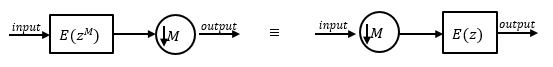
Applying the noble identity for decimation moves the downsampling operation to before the filtering operation. This move enables you to filter the signal at a lower rate.
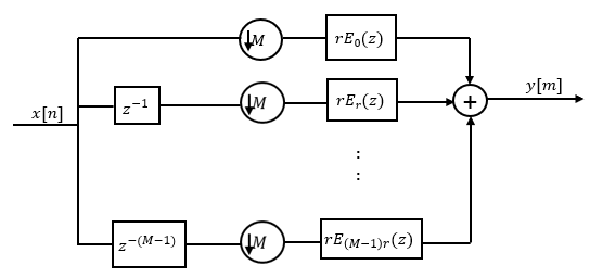
You can replace the delays and the decimation factor at the input with a commutator switch. The switch starts on the first branch 0 and moves in the counterclockwise direction as shown in this diagram. The accumulator at the output receives the processed input samples from each branch of the polyphase structure and accumulates these processed samples until the switch goes to branch 0. When the switch goes to branch 0, the accumulator outputs the accumulated value.

When the first input sample is delivered, the switch feeds this input to the branch 0 and the decimator computes the first output value. As more input samples come in, the switch moves in the counter clockwise direction through branches (M−1)r, (M−2)r, and all the way up to branch 0, delivering one sample at a time to each branch. When the switch comes to branch 0, the decimator outputs the next set of output values. This process continues as data keeps coming in. Every time the switch comes to the branch 0, the decimator outputs y[m]. The decimator effectively outputs one sample for every M samples it receives. Hence the sample rate at the output of the FIR decimation filter is fs/M.
References
[1] Orfanidis, Sophocles J. Introduction to Signal Processing. Upper Saddle River, NJ: Prentice-Hall, 1996.
Extended Capabilities
Version History
Introduced in R2024b