LMS Filter
R2026bLMS Filter block
To add a block to a model, double-click the canvas and start typing the block name. Then, select the block from the list.
Libraries:
DSP HDL Toolbox /
Filtering
Description
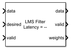
The LMS Filter block estimates the filter weights and minimizes the error between a desired signal and an observed signal using the mean squared error (MSE) criteria. The block adapts its weights until the error between the data and the desired data is minimal. The block accepts scalar and vector inputs of type real and complex. The block supports two architecture options: transposed form delayed least mean square (LMS) and serial direct form LMS.
You can use this block for resource-constrained FPGAs/SoCs and low-throughput applications, such as audio and speech processing as well as for high-throughput FPGA/SoC implementations and high-data-rate applications, such as wireless communications. The block provides an architecture suitable for HDL code generation and hardware deployment.
Note
You can also generate HDL code for this hardware-optimized algorithm, without creating a Simulink® model, by using the DSP HDL IP Designer app. The app provides the same interface and configuration options as the Simulink block.
Examples
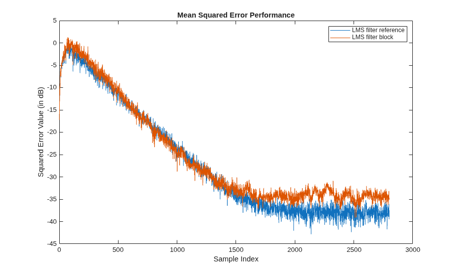
Calculate Mean Square Error Performance Using LMS Filter
How use LMS Filter to calculate mean square error performance in AWGN.
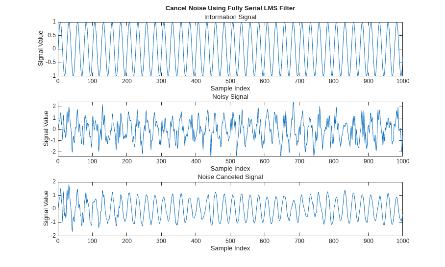
Cancel Noise Using Fully Serial LMS Filter
Cancel additive noise from corrupted signal using LMS Filter.
- Since R2026b
- Open Script
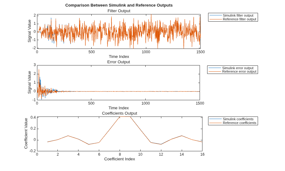
System Identification Using LMS Filter Block
Identify unknown FIR system using LMS Filter.
- Since R2026b
- Open Script
Ports
Input
Input data, specified as a scalar or column vector of real or complex values. The input vector size must be in the range [2, 64] and it must be less than the filter length. The block can only support input word lengths of up to 32 bits.
The Transposed form delayed LMS architecture supports
both scalar and vector inputs, whereas the Serial direct form
LMS architecture supports scalar inputs only.
Use double and single data types for
simulation, but not for HDL code generation. For HDL code generation, the input date
type must be signed fixed point.
Data Types: single | double | fixed point
Complex Number Support: Yes
Desired input data, specified as a scalar or column vector of real or complex values. The input vector size must be in the range [2, 64] and it must be less than filter length. The desired port must have the same data type, complexity, and dimensions as the input data port.
The Transposed form delayed LMS architecture supports
both scalar and vector inputs, whereas the Serial direct form
LMS architecture supports scalar inputs only.
Use double and single data types for
simulation, but not for HDL code generation. For HDL code generation, the input date
type must be signed fixed point.
Data Types: single | double | fixed point
Complex Number Support: Yes
Control signal that indicates if the input data is valid. When
valid is 1 (true), the
block captures the values from the input ports data and
desired. When valid is
0 (false), the block ignores the values from
the input ports data and desired.
Data Types: Boolean
Specify the step size to control convergence and stability of the filter. The recommended step size must be less than 1/(2 x Input power x Filter length).
You can use double and single data types for
simulation, but not for HDL code generation. For HDL code generation, the input date
type must be unsigned fixed point.
Dependencies
To enable this port, on the Main tab, set the
Step-size source parameter to Input
port.
Data Types: double | single | fixed point
When adapt is 1 (true)
and input valid is 1
(true), the block adapts to the new filter weights for every input
valid. When the adapt is
0 (false) and the input
valid is 1 (true) or
0 (false), the block remains at its previous
filter weights.
Dependencies
To enable this port, on the Main tab, select the Enable adapt input port parameter.
Data Types: Boolean
Control signal that clears internal states. When reset is
1 (true), the block stops the current
calculation, clears internal states, and sets to the initial values of filter weights
specified on the block mask. When the reset is
0 (false) and the input
valid is 1 (true), the
block captures data for processing.
For more reset considerations, see the Reset Signal section on the Hardware Control Signals page.
Dependencies
To enable this port, on the Control Ports tab, select the Enable reset input port parameter.
Data Types: Boolean
Output
Filtered output data, returned as a scalar or column vector of real or complex values. The dimensions of the output match the dimensions of the input.
When the input data is a floating-point type, the output data inherits the data type of the input data. When the input data is a fixed-point type, the output data is a fixed point with word length and fractional length incremented by 1.
The block has an output ready signal that indicates when the
block is ready to process new input data when you set the
Architecture parameter to Serial direct form
LMS. Your design can react to the ready signal to
provide the next input sample, or you can space your input data with enough cycles in
between that the block can process each sample. For more information, see Backpressure Signal.
Data Types: single | double | fixed point
Complex Number Support: Yes
Control signal that indicates if the data from the output
data port is valid. When valid is
1 (true), the block returns valid data from
the output data port. When valid is
0 (false), the values from the output
data port are not valid.
Data Types: Boolean
Outputs the result of subtracting the filtered output signal from the desired
signal when the output valid is 1
(true).
If the input data and desired is a scalar or a column vector, the error signal has the same dimension and complexity as the input data. When the input data is a floating-point type, the output data inherits the data type of the input data. When the input data is a fixed-point type, the output data is fixed point with word length incremented by 2 and fractional length incremented by 1.
Dependencies
To enable this port, on the Main tab, select the Enable filter error output port parameter.
Data Types: Boolean
For each iteration, the block outputs the current updated filter weights from this
port when the output valid is 1
(true).
For floating-point inputs, the weights data type must match the input type. For fixed-point signals, the input must match the data type set to the Weights parameter.
Dependencies
To enable this port, on the Main tab, select the Enable filter weights output port parameter.
Data Types: Boolean
Since R2026b
Control signal that indicates the block can accept new input data. The block sets
this output to 1 (true) when it can accept data,
and to 0 (false) when it is processing and
cannot accept more data. For more information, see Backpressure Signal.
Dependencies
To enable this port, set the Architecture parameter to
Serial direct form LMS.
Data Types: Boolean
Parameters
Note
These parameters apply when configuring a block in Simulink or an algorithm in the DSP HDL IP Designer app.
Main
Since R2026b
Select the architecture type.
Serial direct form LMS— Use this option for resource-constrained FPGAs and low-throughput applications, such as audio and speech processing.Transposed form delayed LMS— Use this option for high-throughput FPGA implementations and high-data-rate applications, such as wireless communications.
Specify the length of the LMS filter as a positive integer less than or equal to 2048.
Select whether the block specifies the step size through property or input port.
Property— Specify step size by using the Step size (mu) parameter.Input port— Specify step size by using the stepSize port.
Specify the step size as a positive scalar numeric value. The recommended step size must be less than 1/(2 x Input power x Filter length).
Dependencies
To enable this parameter, set the Step-size source
parameter to Property.
Enter the initial filter weights as a scalar or row vector of size equal to filter length.
When you specify a scalar value, the block considers it as a row vector equivalent to the specified scalar value.
Select this parameter to enable the adapt input port.
Select this parameter to enable the weights output port.
For each iteration, the block outputs the current updated filter weights from this port.
Select this parameter to enable the error output port.
Data Types
Rounding mode for type-casting the output to the data type specified by the Output parameter. When the input data type is floating point, the block ignores this parameter. For more details, see Rounding Modes.
Overflow handling for type-casting the output to the data type specified by the Output parameter. When the input data type is floating point, the block ignores this parameter. For more details, see Overflow Handling.
Specify the step size data type.
Dependencies
To enable this parameter, set the Step-size source
parameter to Property.
Specify the data type for the filter weights.
If you specify an unsigned data type for this parameter, the filter uses the unsigned values and converts them to a signed data type. The signed data type is required to map the design onto DSP slices on an FPGA.
Specify the step size error product.
Control Ports
Select this check box to enable the reset input port. The reset signal implements a local synchronous reset of the data path registers.
For more reset considerations, see the Reset Signal section on the Hardware Control Signals page.
Select this check box to connect the generated HDL global reset signal to the data path registers. This parameter does not change the appearance of the block or modify simulation behavior in Simulink. When you clear this check box, the generated HDL global reset clears only the control path registers. The generated HDL global reset can be synchronous or asynchronous depending on the HDL Code Generation > Global Settings > Reset type parameter in the model Configuration Parameters.
For more reset considerations, see the Reset Signal section on the Hardware Control Signals page.
Algorithms
The following figures show the high-level block diagrams of the LMS Filter
block for Transposed form delayed LMS and Serial
direct form LMS architectures.
Transposed Form Delayed LMS - Scalar
The following figure shows the high-level block diagram of the LMS Filter
block for the Transposed form delayed LMS architecture with scalar
input. An observed signal is provided as input to the Input Memory block and
also to the Transpose Filter block, which is configured with a Discrete
FIR Filter block. The output of the Transpose Filter block is
subtracted from the Desired input signal to output the Filter
Error signal. The Filter Error signal is multiplied with the
Step-Size input signal and the resulted step-error product is converted
to the required data type. The step-error product is multiplied with the corresponding tap
delay line conjugate from the Input Memory block. In the
Integrator block, the multiplied output is added to the previous weight,
Unit Delay, to output new filter weights. These filter weights are
routed back to the Transpose Filter block for the next weight updates.

Serial Direct Form LMS - Scalar
The following figure shows the high-level architecture block diagram of the LMS
Filter block for a Serial direct form LMS architecture
with scalar input. This architecture is similar to the previous configuration, but implements
the non-delayed version of the LMS algorithm. In this structure, the input data is regulated
through a controller so that each weight update is aligned with the next clock-cycle sample of
data. The filter is configured as a partly-serial systolic FIR structure, with
NumCycles = 2 × FilterLength. This choice serializes
the multiply-accumulate operations across multiple clock cycles, reducing hardware
resources.

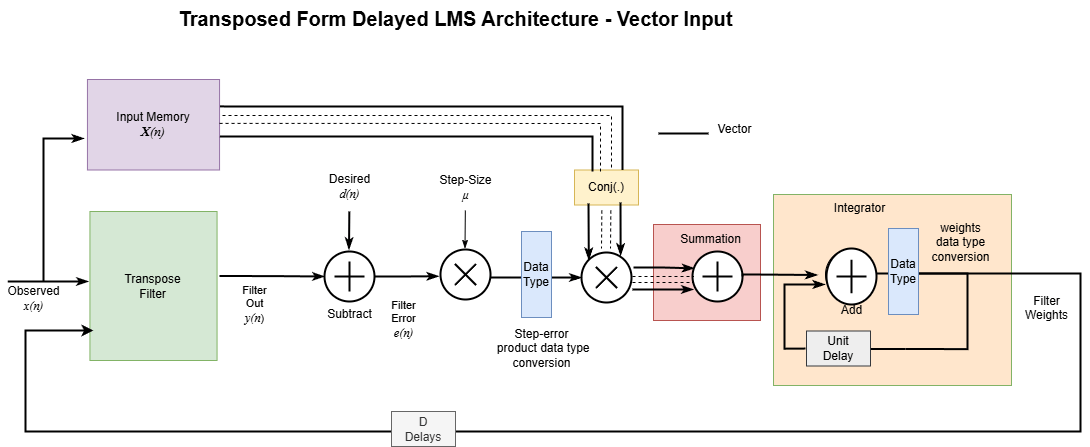
Transposed Form Delayed LMS - Vector
The following figure shows the high-level architecture block diagram of the LMS
Filter block for Transposed form delayed LMS with vector
input. The vector architecture is almost similar to the scalar architecture. In the vector
architecture, step-error product vectors are multiplied with the corresponding tap delay line
conjugates from the Input Memory block and then summed up in the
Summation block. In the Integrator block, the summed output is
added to the previous weight vector Unit Delay to output new filter
weights. These filter weights are routed back to the Transpose Filter block for
the next weight updates.
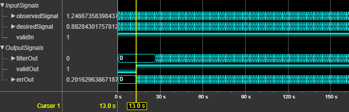
For hardware implementation, all these operations are pipelined, which takes around D number of delays to update the filter weights, where D is the latency of the block.
The latency of the block varies with the input type, architecture type, and filter length.
This figure shows the output of the block for a real scalar input when you set the
Architecture parameter to Transposed form delayed
LMS, Filter length parameter to
64 and all other parameters to their default values. The
latency of the block is 13 clock cycles.
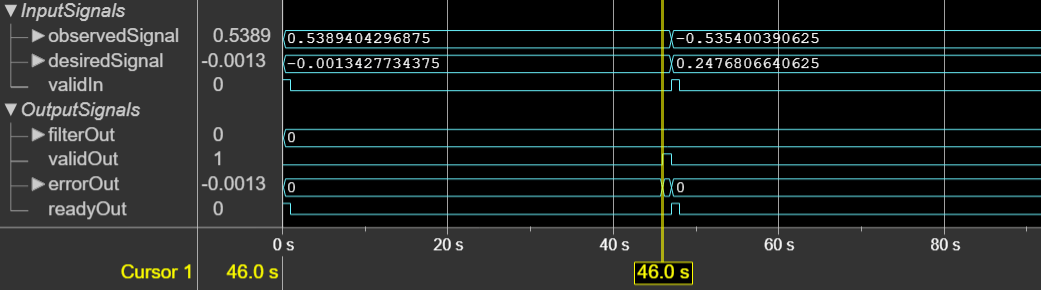
This figure shows the output of the block for a real scalar input when you set the
Architecture parameter to Serial direct form
LMS, Filter length parameter to
16 and all other parameters to their default values. The
latency of the block is 46 clock cycles.
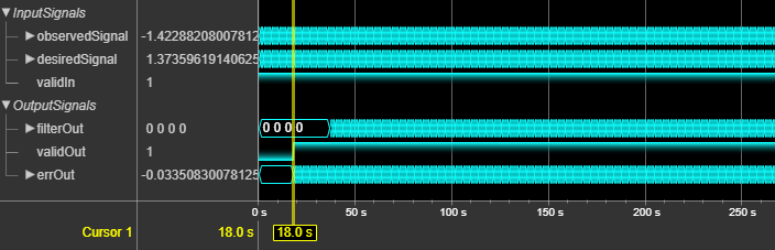
This figure shows the output of the block for a 4-by-1 real vector input when you set
the Architecture parameter to Transposed form delayed
LMS, Filter length parameter to
64 and all other parameters to their default values. The
latency of the block is 18 clock cycles.
The performance of the synthesized HDL code varies with your target and synthesis options. It also varies based on the type of input data and selected configuration. These resource and performance data are the place-and-route results from the generated HDL targeted to an AMD® Zynq® UltraScale+™ MPSoC Evaluation Board.
This table shows the resource and performance data synthesis results of the block for a
scalar input of type fixdt(1,16,0) when you set the
Architecture and Filter length parameters to
Transposed form delayed LMS and 64,
respectively. The design uses these resources and achieves a clock frequency of 523.01 MHz.
| Resource | Number Used |
|---|---|
| LUT | 8402 |
| FFS | 18819 |
AMD LogiCORE® DSP48 | 129 |
This table shows the resource and performance data synthesis results of the block for a
scalar input of type fixdt(1,16,0) when you set the
Architecture and Filter length parameters to
Serial direct form LMS and 64,
respectively. The design uses these resources and achieves a clock frequency of 610
MHz.
| Resource | Number Used |
|---|---|
| LUT | 4925 |
| FFS | 4439 |
AMD LogiCORE DSP48 | 3 |
This table shows the resource and performance data synthesis results of the block for a
4-by-1 vector input when you set the Architecture and Filter
length parameters to Transposed form delayed LMS and
16, respectively. The design uses these resources and achieves
a clock frequency of 512.82 MHz.
| Resource | Number Used |
|---|---|
| LUT | 27712 |
| FFS | 30322 |
AMD LogiCORE DSP48 | 516 |
Using a vector input can increase the throughput, however, doing so also increases the number of hardware resources that the block uses.
References
[1] Hayes, M.H. Statistical Digital Signal Processing and Modeling. New York: John Wiley & Sons, 1996.
Extended Capabilities
This block supports C/C++ code generation for Simulink accelerator and rapid accelerator modes and for DPI component generation.
HDL Coder™ provides additional configuration options that affect HDL implementation and synthesized logic.
This block has one default HDL architecture.
| ConstrainedOutputPipeline | Number of registers to place at
the outputs by moving existing delays in the design. Distributed pipelining
does not redistribute these registers. The default value is
|
| InputPipeline | Number of input pipeline stages
to insert in the generated code. Distributed pipelining and constrained
output pipelining can move these registers. The default value is
|
| OutputPipeline | Number of output pipeline stages
to insert in the generated code. Distributed pipelining and constrained
output pipelining can move these registers. The default value is
|
| SynthesisAttributes |
Specifies the synthesis attributes for the blocks and block output signals in the model. The generated HDL code contains these attributes. For more information, see SynthesisAttributes (HDL Coder). |
Version History
Introduced in R2023aThe LMS Filter block now includes an Architecture
parameter that enables you select either the Transposed form delayed
LMS or Serial direct form LMS architecture. Use
the Serial direct form LMS architecture for resource-constrained
FPGA designs and low-throughput applications, and the Transposed form delayed
LMS architecture for high-throughput FPGA implementations.
MATLAB Command
You clicked a link that corresponds to this MATLAB command:
Run the command by entering it in the MATLAB Command Window. Web browsers do not support MATLAB commands.
选择网站
选择网站以获取翻译的可用内容,以及查看当地活动和优惠。根据您的位置,我们建议您选择:。
您也可以从以下列表中选择网站:
如何获得最佳网站性能
选择中国网站(中文或英文)以获得最佳网站性能。其他 MathWorks 国家/地区网站并未针对您所在位置的访问进行优化。
美洲
- América Latina (Español)
- Canada (English)
- United States (English)
欧洲
- Belgium (English)
- Denmark (English)
- Deutschland (Deutsch)
- España (Español)
- Finland (English)
- France (Français)
- Ireland (English)
- Italia (Italiano)
- Luxembourg (English)
- Netherlands (English)
- Norway (English)
- Österreich (Deutsch)
- Portugal (English)
- Sweden (English)
- Switzerland
- United Kingdom (English)


