Getting Started with Embedded Coder Support Package for Qualcomm Hexagon Processors
R2026bThis example shows how to generate, verify, and profile the optimized code using Embedded Coder® Support Package for Qualcomm® Hexagon® Processors.
In this example, you can run the generated code using Qualcomm Hexagon QHL code replacement library (CRL) and Qualcomm Hexagon HVX CRL for a finite impulse response (FIR) filter on the Qualcomm Hexagon DSP (Qualcomm Hexagon Simulator).
Introduction
The finite impulse response (FIR) filter is a fundamental building block in digital signal processing. The model includes a Gaussian noise source block and a Discrete FIR Filter block.
The Discrete FIR Filter block filters the input signal using the specified filter coefficients. This demonstrates code generation with HVX-optimized CRL replacements.
Required Hardware
Qualcomm Hexagon Simulator
Simulate FIR Filter
The filter coefficients for the Discrete FIR Filter block are designed using the designfilt (Signal Processing Toolbox) function with an equiripple FIR design method. This produces a linear-phase low-pass FIR filter optimized for the specified passband and stopband constraints.
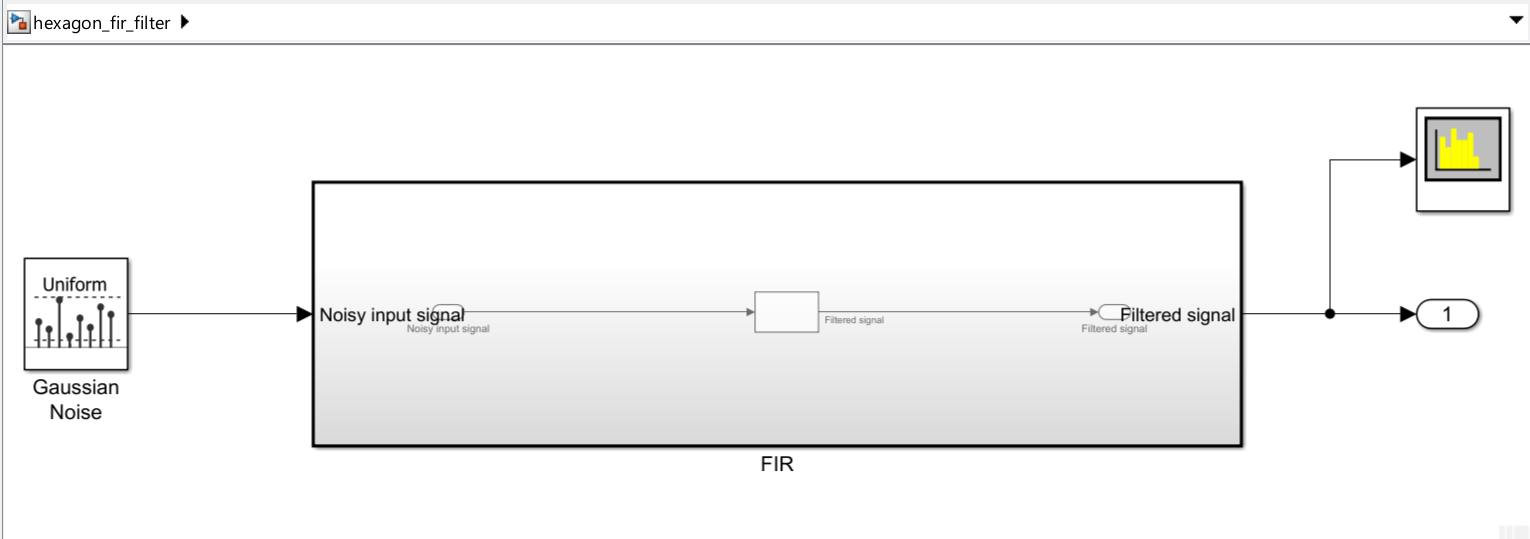
Design Filters for Low Pass Filter Response
Set the filter order to 64, passband frequency to 0.1 (normalized), and stopband frequency to 0.15 (normalized).
FilterOrder = 64;
Fpass = 0.1;   % Normalized passband edge frequency
Fstop = 0.15;  % Normalized stopband edge frequency
Execute these commands to design the equiripple low-pass FIR filter and extract the filter coefficients for the Discrete FIR Filter block.
lpFilter = designfilt('lowpassfir', ...
    'FilterOrder', FilterOrder, ...
    'PassbandFrequency', Fpass, ...
    'StopbandFrequency', Fstop);
h = lpFilter.Coefficients;
Make sure that the commands to compute the filter coefficients are set in the PreLoadFcn of the model. To open and configure PreLoadFcn, follow the below steps:
In the Simulink Toolstrip, on the Modeling tab, click Design gallery and then click Property Inspector.
With no selection at the top level of the model, on the Properties tab click Callbacks section and then select
PreLoadFcn.
To open the model, execute this command:
open_system('hexagon_fir_filter');Observe the magnitude of the FIR filter in the Spectrum Analyzer. For execution in host simulation, click on Run in the Simulation tab or run the following command. The default simulation time is set to 1 sec.
sim('hexagon_fir_filter',SimulationMode="normal");
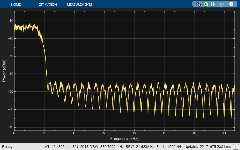
Configure Model
You can configure the model using either the Interactive Approach (Configuration Parameters in Simulink) or the Programmatic Approach (MATLAB® programming interface).
Interactive Approach
Configure the model for code generation on Qualcomm Hexagon Simulator.
Press Ctrl+E to open Configuration Parameters dialog box or on the model toolstrip click the Modeling tab and then click Model Settings.

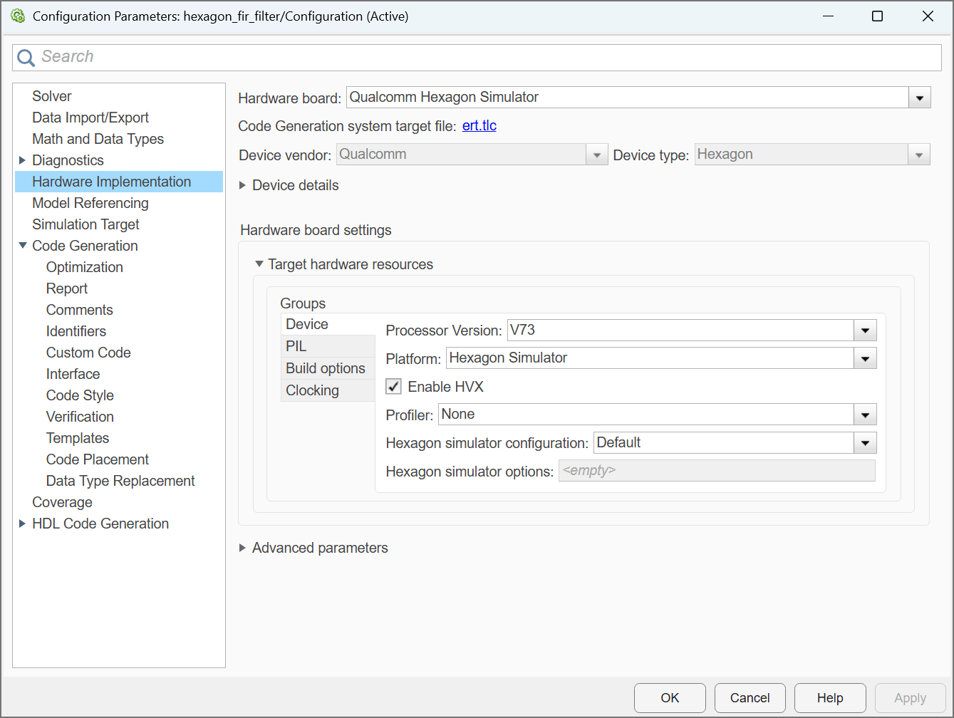
Go to Hardware Implementation > Hardware board and select Qualcomm Hexagon Simulator.
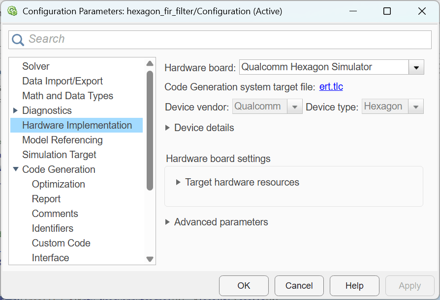
In the Code Generation section, set these parameters:
Under Code Generation > Interface > Code replacement libraries select Qualcomm Hexagon QHL or Qualcomm Hexagon HVX. Make sure that the selected library appears at the top of the list.
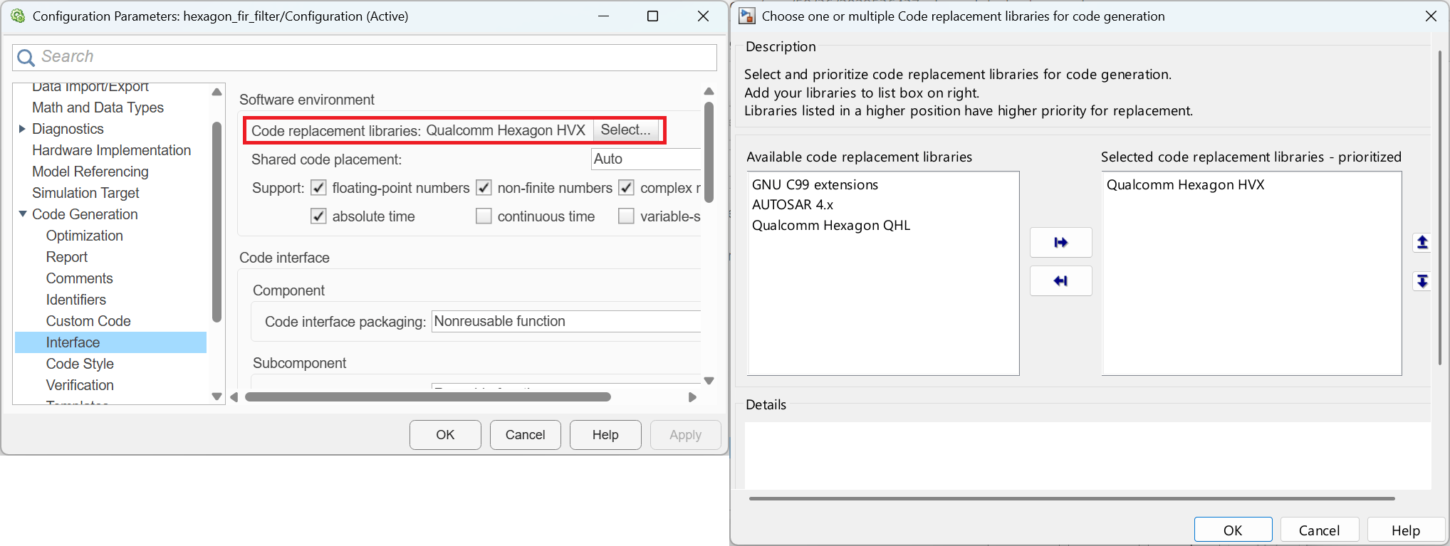
To select the Qualcomm Hexagon HVX library, make sure you select the Enable HVX option located in the Hardware Implementation section, under Hardware Board Settings > Target Hardware Resources. Additionally, the Processor Version must be V68 or higher, as HVX support is limited to these versions. For more information, see Qualcomm Hexagon Simulator Configurations.
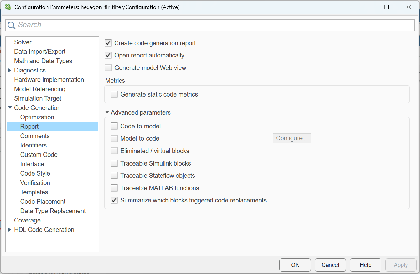
Code Generation > Report > enable Create code generation report
Code Generation > Report > enable Open report automatically
Code Generation > Report > enable Summarize which blocks triggered code replacements
Programmatic Approach
To configure the Simulink model
hexagon_fir_filter.slxfor deployment on Qualcomm Hexagon Simulator, execute these commands:These commands set the system target file to
ert.tlcfor optimizing the code for embedded real-time systems and configure the build configuration to prioritize execution speed by selecting Faster Runs.
set_param('hexagon_fir_filter','HardwareBoard','Qualcomm Hexagon Simulator');
set_param('hexagon_fir_filter','SystemTargetFile','ert.tlc');
set_param('hexagon_fir_filter','BuildConfiguration','Faster Runs');
Set the code replacement library to use either Qualcomm Hexagon QHL for scalar optimizations or Qualcomm Hexagon HVX for vectorized optimizations, in order to produce code that is optimized for Qualcomm Hexagon Simulator.
targetInfo = get_param('hexagon_fir_filter',"CoderTargetData");
targetInfo.Device.EnableHVX = 1;
targetInfo.Device.ProcessorVersion = 'V73';
set_param('hexagon_fir_filter',"CoderTargetData",targetInfo);
set_param('hexagon_fir_filter','CodeReplacementLibrary','Qualcomm Hexagon HVX');
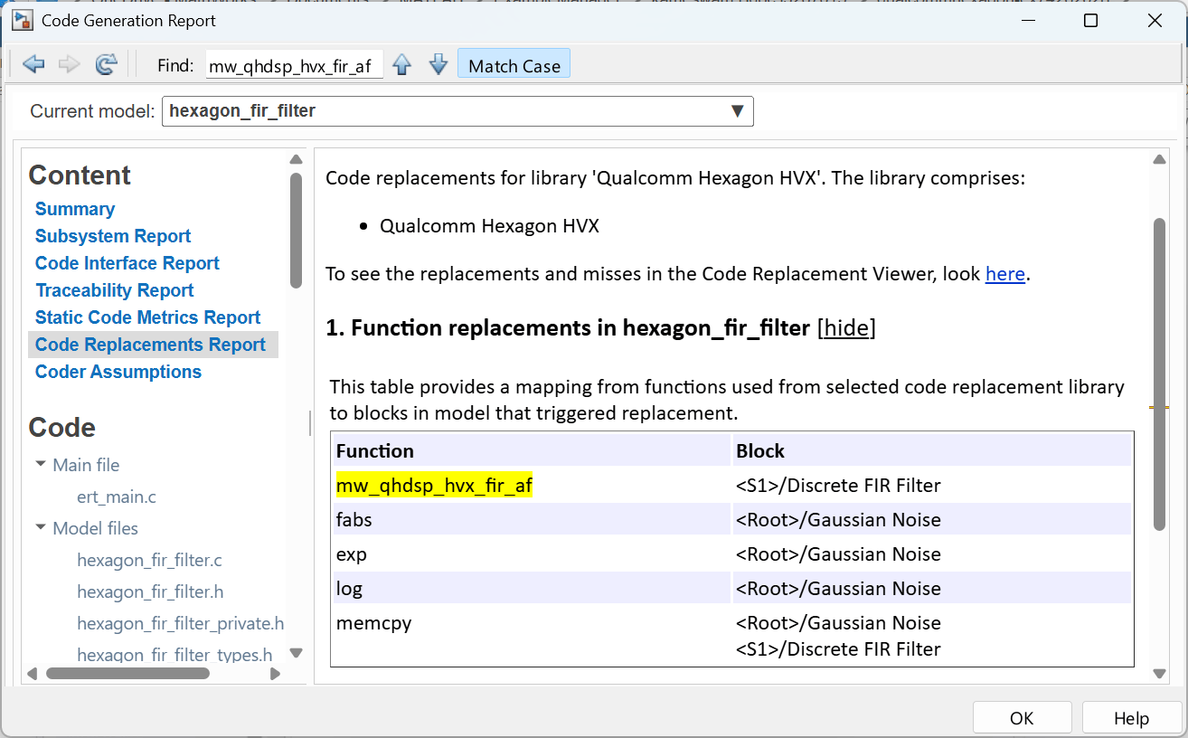
Finally, enable the generation of detailed code replacement reports. These reports provide valuable insights into the code structure and optimizations, facilitating a deeper understanding of the deployment process.
set_param('hexagon_fir_filter','GenerateReport','on');
set_param('hexagon_fir_filter','GenerateCodeReplacementReport','on');
Generate Code
You can now use the model to run the FIR filter on the target.
Press Ctrl+B or go to Embedded Coder App and click Build.

Once the code is generated you can view the generated code by clicking View Code for Qualcomm Hexagon QHL CRL.
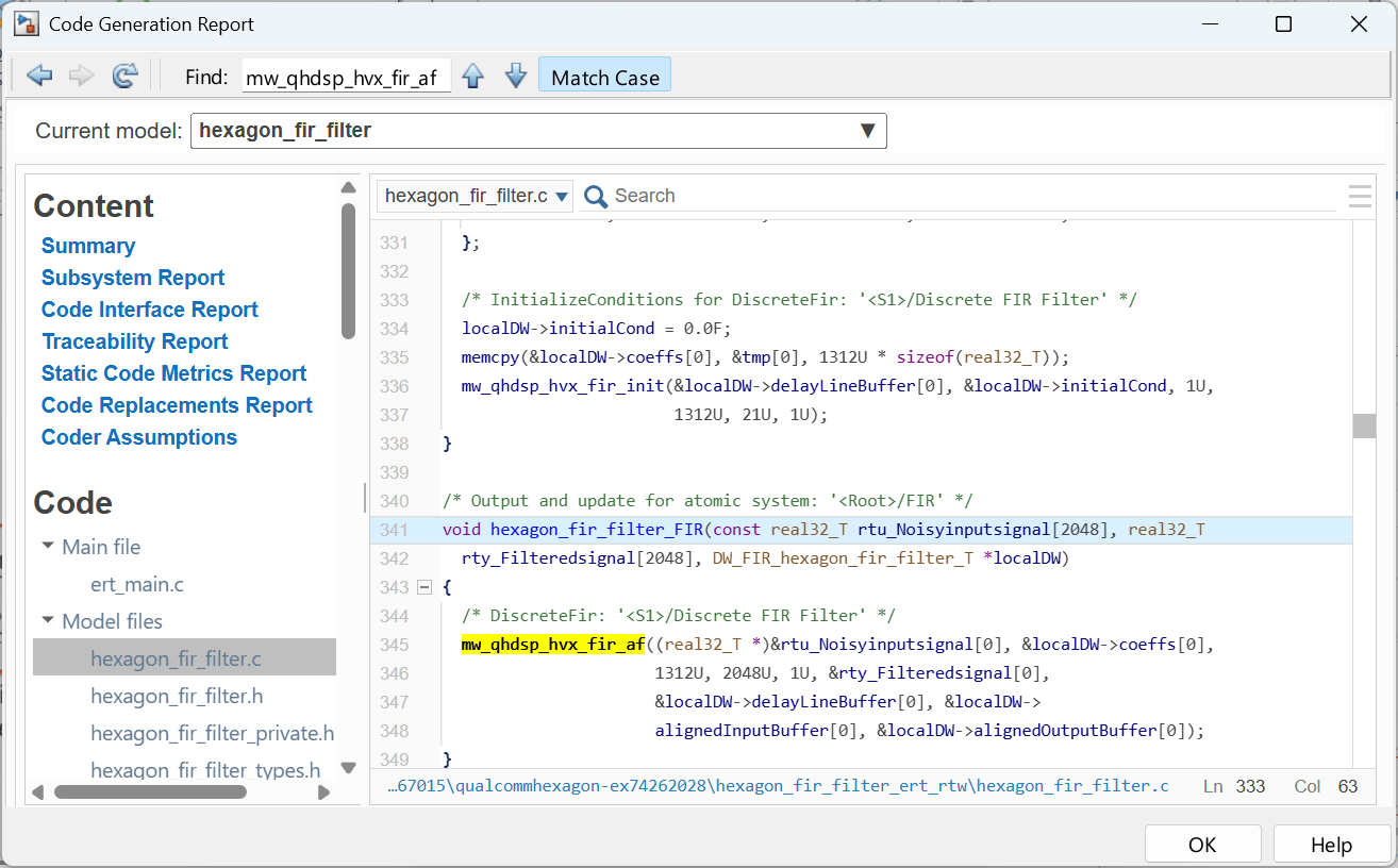
You can also verify the code replacements using the Open Report > Code Replacement Report option.
Verify on Target Using SIL/PIL Manager
To perform numerical accuracy verification of the generated code against the simulation output, use the SIL/PIL Manager App.
Go to SIL/PIL Manager.
Set Mode to Automated Verification.
Set the SIL/PIL Mode to Processor-in-loop (PIL).
Click Run Verification.

Or execute this command to run the model programmatically in PIL mode.
set_param('hexagon_fir_filter','SimulationMode','processor-in-the-loop (pil)');
outputWithCRL = sim('hexagon_fir_filter');
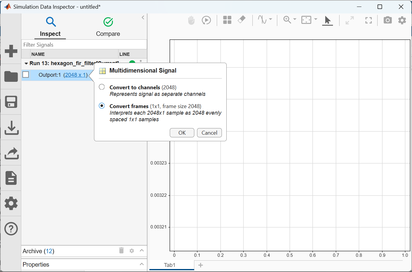
You can verify the numerical accuracy using the Simulation Data Inspector.
First convert the signals into frames in the Inspect tab of the inspector.
Then, verify the accuracy in the Compare tab.
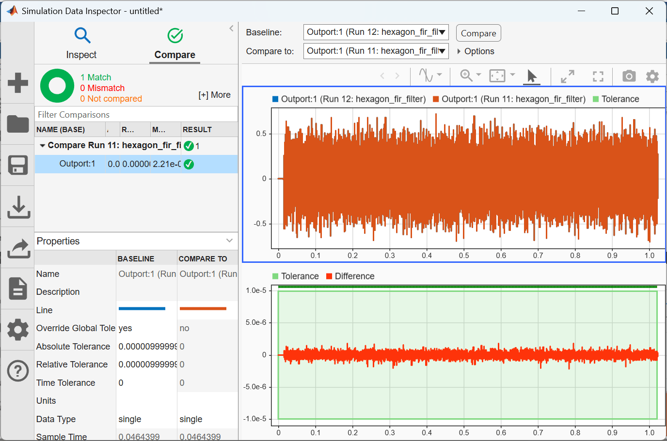
Ensure to set the tolerance (Absolute or Relative) under the [+] More section in the Simulink Data Inspector window.
From the plot, observe that the simulation output overlaps with the PIL output (subplot-1), and the absolute sample tolerance is less than 1e-5 (subplot-2).
Or execute this function to run and configure the SDI programmatically.
simulinkSDI;
Compare Performance
Compare the performance of a particular block with plain C code (without CRL) and QHL/HVX code (with CRL).
Enabling Code Profiling
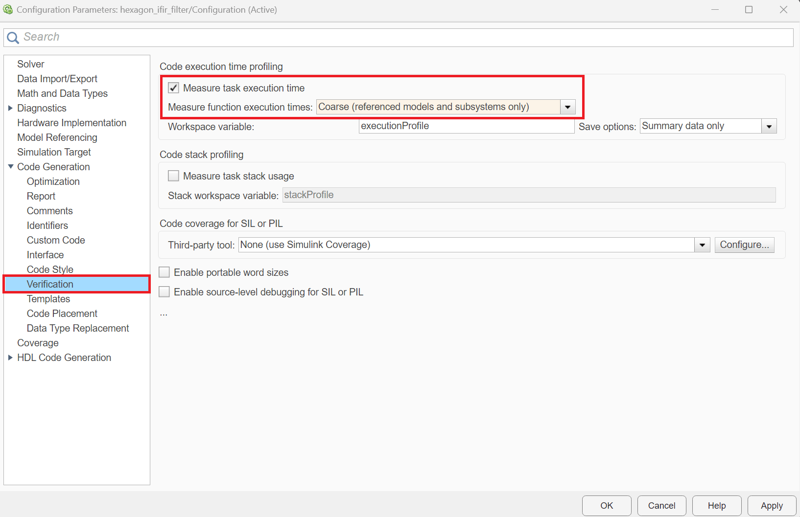
Go to Model Settings, check the Code Generation > Verification > Measure task execution time.
Set Code Generation > Verification > Measure function execution times to Coarse.
Redo the Run Verification step from SIL/PIL.
Code Profile Analyzer
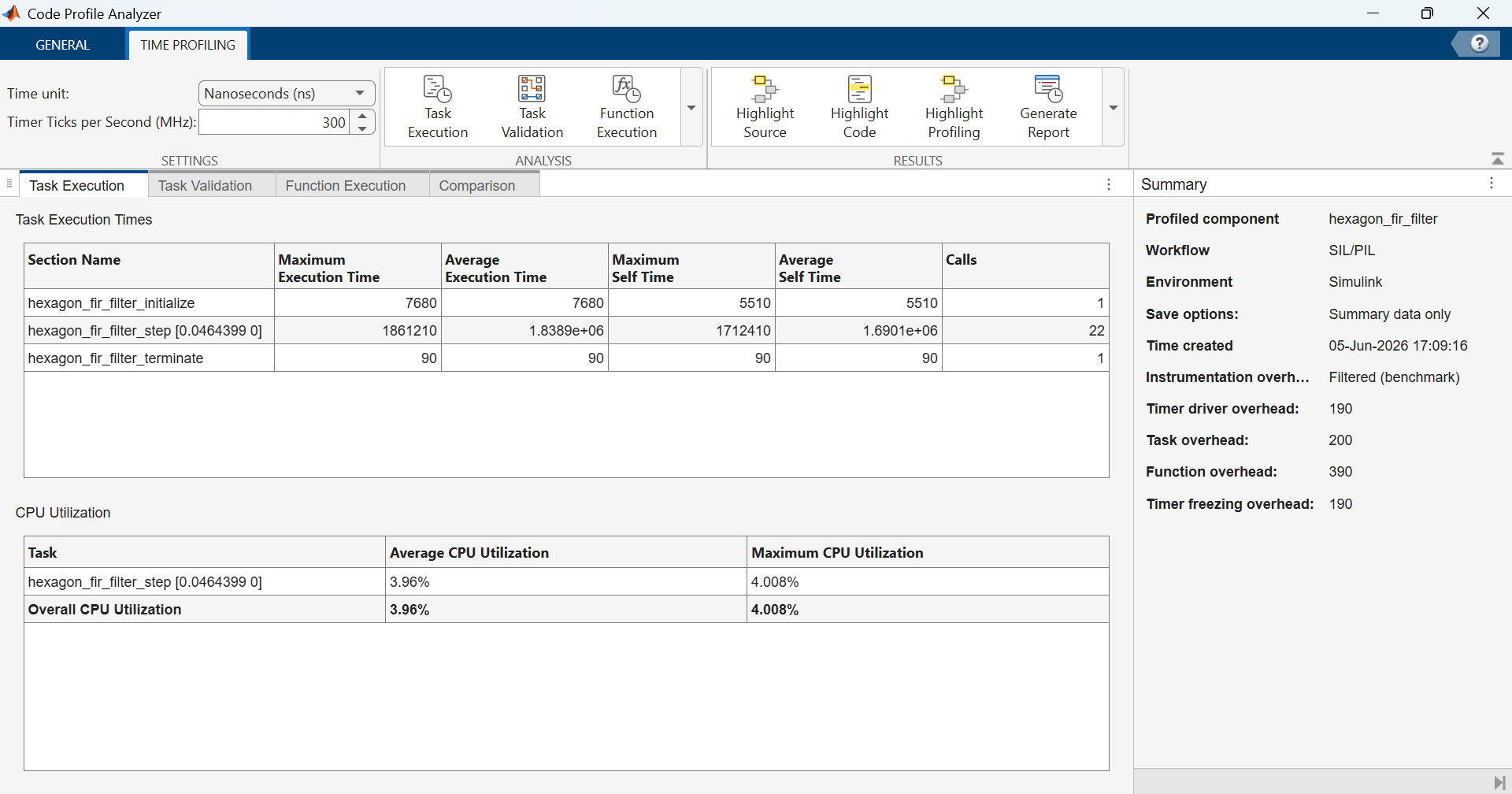
To analyze the profiling information, you can use Code Profile Analyzer.
Under the Analysis section, click Function Execution.
In the Function Execution Times pane, verify the Maximum and Average Execution time for the Discrete FIR Filter block and Math Operations. You can consider the average execution time for the whole simulation.
Optionally, you can also verify the relative times among the self-time/caller or self-time/task.
This image shows the code profile analyzer report for Qualcomm Hexagon HVX CRL replacements.
stepIdx = contains({outputWithCRL.get('executionProfile').Sections.Name}, '_step');
ticksWithHVXCRL = outputWithCRL.get('executionProfile').Sections(stepIdx).TotalExecutionTimeInTicks;
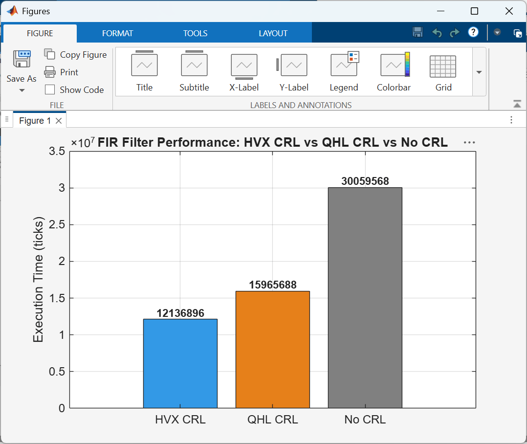
You can observe that the total execution time in ticks consumed by the step function with Qualcomm Hexagon HVX CRL is 12136896 cycles. Repeat the same steps without selecting a CRL in the Model Settings (Code Generation > Interface > Code replacement libraries).
set_param('hexagon_fir_filter','CodeReplacementLibrary','Qualcomm Hexagon QHL');
outputWithQHLCRL = sim('hexagon_fir_filter');
stepIdx = contains({outputWithQHLCRL.get('executionProfile').Sections.Name}, '_step');
ticksWithQHLCRL = outputWithQHLCRL.get('executionProfile').Sections(stepIdx).TotalExecutionTimeInTicks;


set_param('hexagon_fir_filter','CodeReplacementLibrary','None');
outputWithoutCRL = sim('hexagon_fir_filter');
stepIdx = contains({outputWithoutCRL.get('executionProfile').Sections.Name}, '_step');
ticksWithoutCRL = outputWithoutCRL.get('executionProfile').Sections(stepIdx).TotalExecutionTimeInTicks;
The total cycles consumed by the step function without selecting a CRL is around 30059568 cycles.
Similarly, the total execution time in ticks consumed by the step function with Qualcomm Hexagon QHL CRL is 15965688 cycles. This figure shows the performance comparison between the Qualcomm Hexagon QHL CRL, Qualcomm Hexagon HVX CRL, and Plain-C.
See Also
Launch Hardware Setup | Qualcomm Hexagon Simulator Configurations

