Main Content

insfilterErrorState

Estimate pose from IMU, GPS, and monocular visual odometry (MVO) data

Description

The insfilterErrorState object implements sensor fusion of IMU, GPS, and monocular visual odometry (MVO) data to estimate pose in the NED (or ENU) reference frame. The filter uses a 17-element state vector to track the orientation quaternion, velocity, position, IMU sensor biases, and the MVO scaling factor. The insfilterErrorState object uses an error-state Kalman filter to estimate these quantities.

Creation

Description

filter = insfilterErrorState creates an insfilterErrorState object with default property values.

example

filter = insfilterErrorState('ReferenceFrame',RF) allows you to specify the reference frame, RF, of the filter.

filter = insfilterErrorState(___,Name=Value) sets one or more properties using name-value arguments in addition to any of the previous input arguments.

Input Arguments

expand all

Local navigation coordinate system, specified as either 'NED' (North-East-Down) or 'ENU' (East-North-Up).

Data Types: char | string

Properties

expand all

Sample rate of the inertial measurement unit (IMU) in Hz, specified as a positive scalar.

Data Types: single | double

Reference location, specified as a 3-element row vector in geodetic coordinates (latitude, longitude, and altitude). Altitude is the height above the reference ellipsoid model, WGS84. The reference location units are [degrees degrees meters].

Data Types: single | double

Multiplicative process noise variance from the gyroscope in (rad/s)2, specified as a scalar or 3-element row vector of positive real finite numbers.

  • If GyroscopeNoise is specified as a row vector, the elements correspond to the noise in the x, y, and z axes of the gyroscope, respectively.

  • If GyroscopeNoise is specified as a scalar, the single element is applied to each axis.

Data Types: single | double

Additive process noise variance from the gyroscope bias in (rad/s)2, specified as a scalar or 3-element row vector of positive real finite numbers.

  • If GyroscopeBiasNoise is specified as a row vector, the elements correspond to the noise in the x, y, and z axes of the gyroscope, respectively.

  • If GyroscopeBiasNoise is specified as a scalar, the single element is applied to each axis

Data Types: single | double

Multiplicative process noise variance from the accelerometer in (m/s2)2, specified as a scalar or 3-element row vector of positive real finite numbers.

  • If AccelerometerNoise is specified as a row vector, the elements correspond to the noise in the x, y, and z axes of the accelerometer, respectively.

  • If AccelerometerNoise is specified as a scalar, the single element is applied to each axis.

Data Types: single | double

Additive process noise variance from accelerometer bias in (m/s2)2, specified as a scalar or 3-element row vector of positive real numbers.

  • If AccelerometerBiasNoise is specified as a row vector, the elements correspond to the noise in the x, y, and z axes of the accelerometer, respectively.

  • If AccelerometerBiasNoise is specified as a scalar, the single element is applied to each axis.

State vector of the extended Kalman filter, specified as a 17-element column vector. The state values represent:

StateUnitsIndex
Orientation (quaternion parts)N/A1:4
Position (NED or ENU)m5:7
Velocity (NED or ENU)m/s8:10
Gyroscope Bias (XYZ)rad/s11:13
Accelerometer Bias (XYZ)m/s214:16
Visual Odometry Scale (XYZ)N/A17

The default initial state corresponds to an object at rest located at [0 0 0] in geodetic LLA coordinates.

Data Types: single | double

State error covariance for the Kalman filter, specified as a 16-by-16-element matrix of real numbers. The state error covariance values represent:

State CovarianceRow/Column Index
δ Rotation Vector (XYZ)1:3
δ Position (NED or ENU)4:6
δ Velocity (NED or ENU)7:9
δ Gyroscope Bias (XYZ)10:12
δ Accelerometer Bias (XYZ)13:15
δ Visual Odometry Scale (XYZ)16

Note that because this is an error-state Kalman filter, it tracks the errors in the states. δ represents the error in the corresponding state.

Data Types: single | double

Object Functions

predictUpdate states using accelerometer and gyroscope data for insfilterErrorState
correctCorrect states using direct state measurements for insfilterErrorState
residualResiduals and residual covariances from direct state measurements for insfilterErrorState
fusegpsCorrect states using GPS data for insfilterErrorState
residualgpsResiduals and residual covariance from GPS measurements for insfilterErrorState
fusemvoCorrect states using monocular visual odometry for insfilterErrorState
residualmvoResiduals and residual covariance from monocular visual odometry measurements for insfilterErrorState
poseCurrent orientation and position estimate for insfilterErrorState
resetReset internal states for insfilterErrorState
stateinfoDisplay state vector information for insfilterErrorState
tuneTune insfilterErrorState parameters to reduce estimation error
copyCreate copy of insfilterErrorState

Examples

collapse all

Load logged data of a ground vehicle following a circular trajectory. The .mat file contains IMU and GPS sensor measurements and ground truth orientation and position.

load('loggedGroundVehicleCircle.mat', ...
    'imuFs','localOrigin', ...
    'initialStateCovariance', ...
    'accelData','gyroData', ...
    'gpsFs','gpsLLA','Rpos','gpsVel','Rvel', ...
    'trueOrient','truePos');

Create an INS filter to fuse IMU and GPS data using an error-state Kalman filter.

initialState = [compact(trueOrient(1)),truePos(1,:),-6.8e-3,2.5002,0,zeros(1,6),1].';
filt = insfilterErrorState;
filt.IMUSampleRate = imuFs;
filt.ReferenceLocation = localOrigin;
filt.State = initialState;
filt.StateCovariance = initialStateCovariance;

Preallocate variables for position and orientation. Allocate a variable for indexing into the GPS data.

numIMUSamples = size(accelData,1);
estOrient = ones(numIMUSamples,1,'quaternion');
estPos = zeros(numIMUSamples,3);

gpsIdx = 1;

Fuse accelerometer, gyroscope, and GPS data. The outer loop predicts the filter forward at the fastest sample rate (the IMU sample rate).

for idx = 1:numIMUSamples

    % Use predict to estimate the filter state based on the accelData and
    % gyroData arrays.
    predict(filt,accelData(idx,:),gyroData(idx,:));
    
    % GPS data is collected at a lower sample rate than IMU data. Fuse GPS
    % data at the lower rate.
    if mod(idx, imuFs / gpsFs) == 0
        % Correct the filter states based on the GPS data.
        fusegps(filt,gpsLLA(gpsIdx,:),Rpos,gpsVel(gpsIdx,:),Rvel);
        gpsIdx = gpsIdx + 1;
    end
    
    % Log the current pose estimate
    [estPos(idx,:), estOrient(idx,:)] = pose(filt);
end

Calculate the RMS errors between the known true position and orientation and the output from the error-state filter.

pErr = truePos - estPos;
qErr = rad2deg(dist(estOrient,trueOrient));

pRMS = sqrt(mean(pErr.^2));
qRMS = sqrt(mean(qErr.^2));

fprintf('Position RMS Error\n');
Position RMS Error
fprintf('\tX: %.2f, Y: %.2f, Z: %.2f (meters)\n\n',pRMS(1),pRMS(2),pRMS(3));
	X: 0.40, Y: 0.24, Z: 0.05 (meters)
fprintf('Quaternion Distance RMS Error\n');
Quaternion Distance RMS Error
fprintf('\t%.2f (degrees)\n\n',qRMS);
	0.30 (degrees)

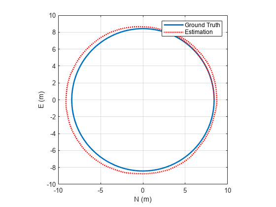
Visualize the true position and the estimated position.

plot(truePos(:,1),truePos(:,2),estPos(:,1),estPos(:,2),'r:','LineWidth',2)
grid on
axis square
xlabel('N (m)')
ylabel('E (m)')
legend('Ground Truth','Estimation')

Figure contains an axes object. The axes object with xlabel N (m), ylabel E (m) contains 2 objects of type line. These objects represent Ground Truth, Estimation.

Algorithms

Note: The following algorithm only applies to an NED reference frame.

insfilterErrorState uses a 17-axis error state Kalman filter structure to estimate pose in the NED reference frame. The state is defined as:

x=[q0q1q2q3positionNpositionEpositionDvNvEvDgyrobiasXgyrobiasYgyrobiasZaccelbiasXaccelbiasYaccelbiasZscaleFactor]

where

  • q0, q1, q2, q3 –– Parts of orientation quaternion. The orientation quaternion represents a frame rotation from the platform's current orientation to the local NED coordinate system.

  • positionN, positionE, positionD –– Position of the platform in the local NED coordinate system.

  • gyrobiasX, gyrobiasY, gyrobiasZ –– Bias in the gyroscope reading.

  • accelbiasX, accelbiasY, accelbiasZ –– Bias in the accelerometer reading.

  • scaleFactor –– Scale factor of the pose estimate.

Given the conventional formulation of the state transition function,

xk|k1=f(x^k1|k1)

the predicted state estimate is:

xk|k1=[q0+Δtq1(gyrobiasX/2gyroX/2)+Δtq2(gyrobiasY/2gyroY/2)+Δtq3(gyrobiasZ/2gyroZ/2)q1Δtq0(gyrobiasX/2gyroX/2)+Δtq3(gyrobiasY/2gyroY/2)Δtq2(gyrobiasZ/2gyroZ/2)q2Δtq3(gyrobiasX/2gyroX/2)Δtq0(gyrobiasY/2gyroY/2)+Δtq1(gyrobiasZ/2gyroZ/2)q3+Δtq2(gyrobiasX/2gyroX/2)Δtq1(gyrobiasY/2gyroY/2)Δtq0(gyrobiasZ/2gyroZ/2)positionN+ΔtvNpositionE+ΔtvEpositionD+ΔtvDvNΔt{q0(q0(accelbiasXaccelX)q3(accelbiasYaccelY)+q2(accelbiasZaccelZ))+gN+q2(q1(accelbiasYaccelY)q2(accelbiasXaccelX)+q0(accelbiasZaccelZ))+q1(q1(accelbiasXaccelX)+q2(accelbiasYaccelY)+q3(accelbiasZaccelZ))q3(q3(accelbiasXaccelX)+q0(accelbiasYaccelY)q1(accelbiasZaccelZ))}vEΔt{q0(q3(accelbiasXaccelX)+q0(accelbiasYaccelY)q1(accelbiasZaccelZ))+gEq1(q1(accelbiasYaccelY)q2(accelbiasXaccelX)+q0(accelbiasZaccelZ))+q2(q1(accelbiasXaccelX)+q2(accelbiasYaccelY)+q3(accelbiasZaccelZ))+q3(q0(accelbiasXaccelX)q3(accelbiasYaccelY)+q2(accelbiasZaccelZ))}vDΔt{q0(q1(accelbiasYaccelY)q2(accelbiasXaccelX)+q0(accelbiasZaccelZ))+gD+q1(q3(accelbiasXaccelX)+q0(accelbiasYaccelY)q1(accelbiasZaccelZ))q2(q0(accelbiasXaccelX)q3(accelbiasYaccelY)+q2(accelbiasZaccelZ))q3(q1(accelbiasXaccelX)+q2(accelbiasYaccelY)+q3(accelbiasZaccelZ))}gyrobiasXgyrobiasYgyrobiasZaccelbiasXaccelbiasYaccelbiasZscaleFactor]

where

  • Δt –– IMU sample time.

  • gN, gE, gD –– Constant gravity vector in the NED frame.

Extended Capabilities

C/C++ Code Generation
Generate C and C++ code using MATLAB® Coder™.

Version History

Introduced in R2019a