Replace Piecewise-Constant Resistor with Switched Linear Components
This example shows how to convert a Simscape™ model that has a Piecewise-Constant Resistor (nonlinear component) into a switched linear model, making it compatible with Simscape Hardware-in-the-Loop (HIL) workflow.
Introduction
Simscape HIL workflow supports conversion of Simscape models to functionally equivalent Simulink® models that are compatible for HDL code generation. In this example, the model uses a Piecewise-Constant Resistor that is event based. Events are not supported by the Simscape HIL workflow. You can convert such Simscape models to a switched linear model and make it compatible for HDL code generation. For more information, see Generate and Validate HDL Code for Simscape Model.
Open the Simscape model from the MATLAB® command prompt.
NonlinearModel = 'sschdlexVariableResistorExample';
open_system(NonlinearModel)
set_param(NonlinearModel, 'SimulationCommand', 'update');

Open the Simscape subsystem.
open_system([NonlinearModel,'/Simscape Subsystem'])
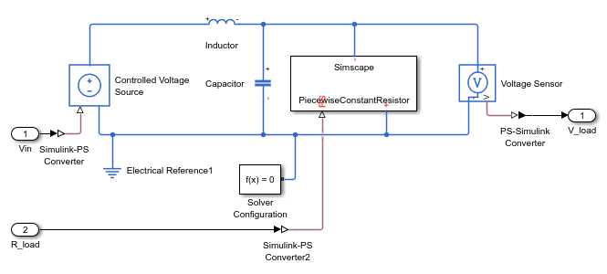
This model is an RLC circuit with a Piecewise-Constant Resistor acting as a "Load" resistance. For the Piecewise-Constant Resistor, the relationship between voltage  and current
  is
is  , where
  is the numerical value presented at the physical signal port .
To ensure a positive value for the resistance, any value below 1e-6 is replaced by 1e-6. This resistor is piecewise-constant because the resistance only changes when the input value differs from the current resistance value by more than the set tolerance. Thus, a continuously changing input is converted to a discrete set of resistances.
In this model, the signal going into the Piecewise-Constant Resistor is a step function that changes from 2 to 3 at t = 0.1 thus changing the load resistance from 2 Ω to 3 Ω.

Open the Simscape HDL Workflow Advisor using sschdladvisor function.
sschdladvisor(NonlinearModel)
In the Simscape HDL Workflow Advisor, right-click the Code generation compatibility > Check model compatibility task and select Run to Selected Task. This task fails because of the presence of the Piecewise-Constant Resistor.

Replace Piecewise-Constant Resistor with Switches and Constant Resistors
To convert this model to an equivalent switched linear model, replace the Piecewise-Constant Resistor with a set of switches and resistors for each desired value. Open the switched linear version of the model.
SwitchedLinearModel = 'sschdlexVariableResistorSwitchedLinearExample';
open_system(SwitchedLinearModel)
set_param(SwitchedLinearModel, 'SimulationCommand', 'update');

Instead of a Piecewise-Constant Resistor, the model uses a resistor and a switch for each desired resistance. In particular, it uses a resistance of 2 Ω and the other with a resistance of 3 Ω. By closing and opening the switches at t = 0.1, the model changes the load resistance from 2 Ω to 3 Ω.
open_system([SwitchedLinearModel,'/Simscape Subsystem'])

Controlling the Switches
Open the control signals for the switches.
open_system([SwitchedLinearModel,'/Input'])
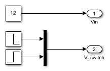
The input signal V_switch contains two step functions, one that opens the switch in series with the 2 Ω resistor at t = 0.1 and one that closes the switch in series with the 3 Ω resistor at the same time.
Generate HDL Implementation Model
Use the default Solver Configuration settings for the switched linear model:
Solver type:
Backward EulerSample time:
1e-3
In the model window, you can view the model statistics. Select the Debug tab and click Simscape > Statistics Viewer. This opens the Simscape Statistics window for sschdlexVariableResistorExample model.
Open the Simscape HDL Workflow Advisor for the switched linear model.
sschdladvisor(SwitchedLinearModel)
To generate the HDL implementation model, right-click the Implementation model generation > Generate implementation model task, and then select Run to Selected Task.
After the last task passes, it creates a link to the HDL implementation model gmStateSpaceHDL_sschdlexVariableResistorSwi.
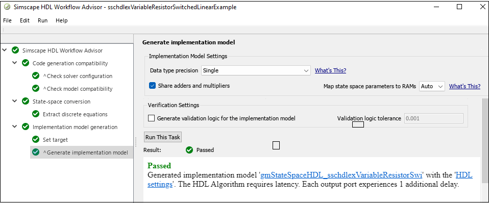
Click on this link to open the generated implementation model.
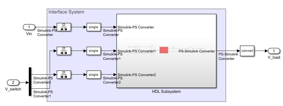
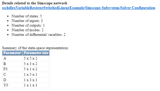
In the right pane, the Extract discrete equations task output displays the number of states, inputs, outputs, modes, differential variables, and state-space representation for the Simscape network.
Generate HDL Code
To set up model parameters for HDL code generation, run the hdlsetup function.
hdlsetup('gmStateSpaceHDL_sschdlexVariableResistorSwi')
Save the parameters for the HDL implementation model.
hdlsaveparams('gmStateSpaceHDL_sschdlexVariableResistorSwi')
Enable generation of the resource utilization report.
hdlset_param('gmStateSpaceHDL_sschdlexVariableResistorSwi', 'ResourceReport', 'on')
hdlset_param('gmStateSpaceHDL_sschdlexVariableResistorSwi', 'MaskParameterAsGeneric', 'off');
Generate HDL code for the implementation model.
makehdl('gmStateSpaceHDL_sschdlexVariableResistorSwi/Simscape Subsystem/HDL Subsystem');
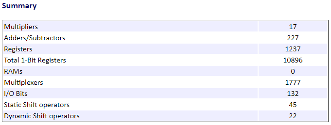
When you generate code, HDL Coder creates a code generation report. The resource utilization report in the High-level Resource Report indicates the number of adders, multipliers, and registers that might be consumed on the target FPGA device.
By changing the Piecewise-Constant Resistor to resistors that switch on and off, you change the model to a form that is compatible with the Simscape to HDL workflow.