Use Clock Domain Crossing to Run DUT Algorithm and AXI4-Lite Interface at Different Frequencies
In many applications, high-speed data processing is essential. However, configuring these designs through a register interface, such as updating coefficients in an FIR filter, does not require the same high performance. When the device under test (DUT) algorithm and the register interface operate at the same high frequency, you may find it harder to meet timing closure.
This example demonstrates how to use clock domain crossing (CDC) to meet timing requirements when interfacing a high-speed DUT algorithm with a slower AXI4-Lite register interface using HDL Coder™. CDC is a critical aspect of FPGA design, especially when different parts of a system operate at disparate frequencies. By incorporating CDC and back-pressure logic, HDL Coder can insert the necessary logic for communication between clock domains and mitigate the risk of data corruption and timing violations. The example demonstrates how adjusting the register interface to a slower frequency and enabling CDC can allow the design to achieve timing closure.
Generate HDL IP Core with AXI4-Lite Interface
The example model ProgrammableFIRCDC has a subsystem named HDL Algorithm that has a control signal that switches between two sets of coefficients. The HDL Algorithm subsystem includes a Discrete FIR Filter block, and the coefficients used in the filter are defined by the vector inputs.
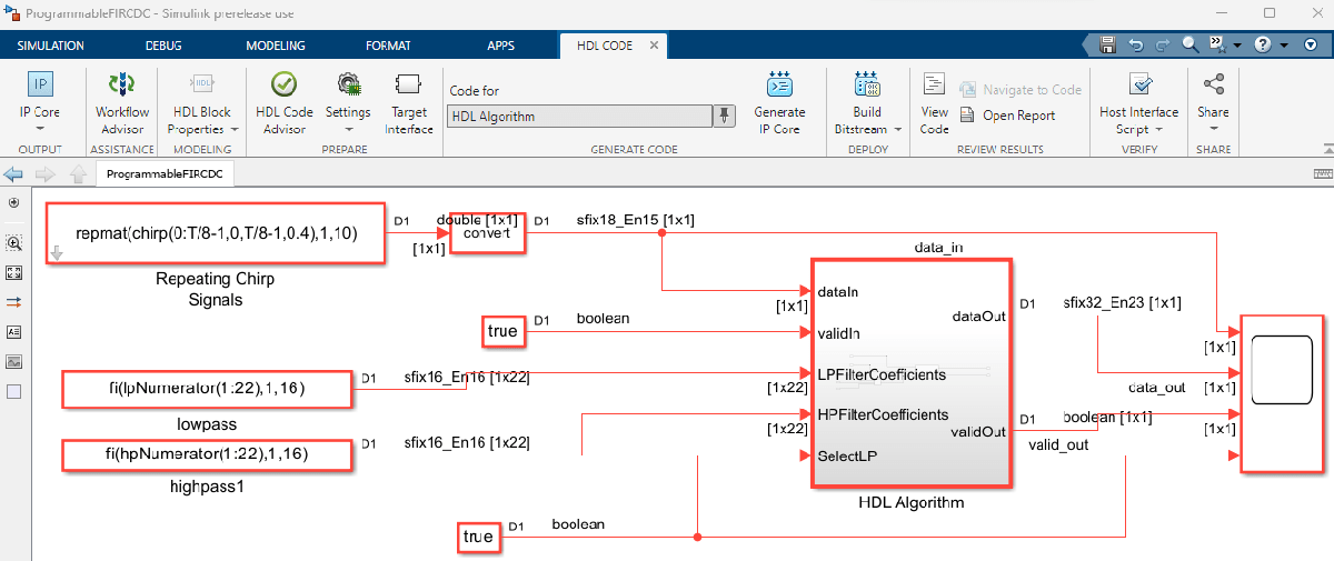
To enable simulation and testing, this model contains two FIR filters, one with a low-pass response and one with a complementary high-pass response. Both filters are odd-symmetric and have 43 taps. The design specifications for both filters are:
Fpass = 0.45; % Passband frequency
Fstop = 0.55; % Stopband frequency
Apass = 1;    % Passband attenuation (dB)
Astop = 60;   % Stopband attenuation (dB)

f = fdesign.lowpass('Fp,Fst,Ap,Ast',Fpass,Fstop,Apass,Astop);
Hlp = design(f,'equiripple','FilterStructure','dffir'); % Lowpass
Hhp = firlp2hp(Hlp);                                    % Highpass

hpNumerator = Hlp.Numerator;
lpNumerator = Hhp.Numerator;
To generate an IP core from the ProgrammableFIRCDC/HDL Algorithm subsystem, prepare the model by using the configuration parameters, configure your design using the IP Core editor, and generate the bitstream using the HDL Code tab of the Simulink® Toolstrip:
In the Apps tab, click HDL Coder. In the HDL Code tab, in the Output section, set the drop-down button to IP Core.
Select the
HDL Algorithmsubsystem which is the DUT for this example. In the HDL Code tab, ensure that Code for is set to this subsystem. To remember the selection, you can pin this option.Open the HDL Code Generation > Target tab of Configuration Parameters dialog box by clicking the Settings button.
Set the Target Platform parameter to
ZedBoard. If this option does not appear, selectGet moreto open the Support Package Installer. In the Support Package Installer, selectHDL Coder Support Package for AMD FPGA and SoC Devicesand follow the instructions to complete the installation.Set the Synthesis Tool to
Xilinx Vivado.Set the Reference Design parameter to
Default system with AXI4-Stream Interfaceand Target Frequency to129.Click OK to save your updated settings.
The Default system with AXI4-Stream Interface reference design is configured to use the same clock for the DUT and the AXI4 register interface. The next section demonstrates that using the same high clock frequency for the whole design does not achieve timing closure.
Configure Design and Target Interface
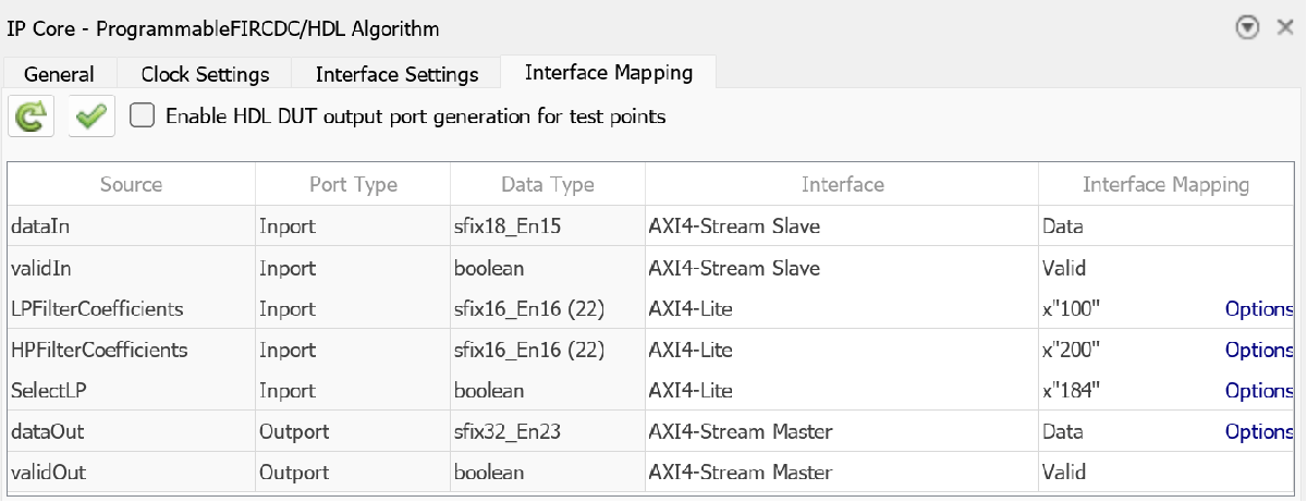
Configure the design to map to the target hardware by mapping the DUT ports to the IP core target hardware and setting the DUT-level IP core options. In this example, map the DUT ports LPFilterCoefficients, HPFilterCoefficients, and SelectLP to AXI4-Lite and map the dataIn, ValidIn, dataOut, and ValidOut interfaces to AXI4-Stream.
In Simulink, in the HDL Code tab, click Target Interface to open the IP Core editor.
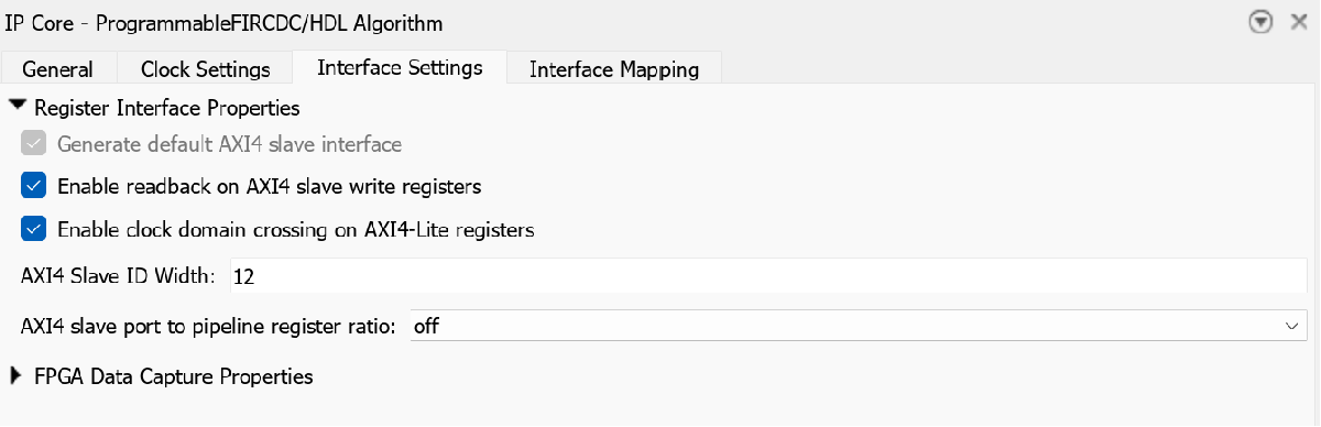
In the IP Core pane, select Interface Settings. Ensure that Enable readback on the AXI4 registers is selected and set the AXI4 Subordinate port to pipeline register ratio to
off.Select the Interface Mapping tab to map each DUT port to one of the IP core target interfaces. The generated design can then communicate with the rest of the hardware system when it is deployed. If no mapping table appears, click the Reload IP core settings and interface mapping table from model button
 to compile the model and repopulate the DUT ports and their data types.
For the DUT ports LPFilterCoefficients, HPFilterCoefficients, and SelectLP, set the cells in the Interface column to
AXI4-Lite.For the DUT ports dataIn, ValidIn, dataOut, and ValidOut, set the Interface column to
AXI4-Stream.Validate your settings by clicking the Validate IP core settings and interface mapping button
 .
.
After you configure the IP core settings and mappings, you can generate the bitstream. To generate the bitstream file, in the Simulink Toolstrip, in the HDL Code tab, click Build Bitstream and wait until the synthesis tool runs in the external window.
The generated HDL code fails to meet the 129 MHz timing requirement for the clock. The timing requirement is 7.752 ns, or 1/129MHz. In this example, the synthesis tool reported a negative slack, which indicates a timing violation.
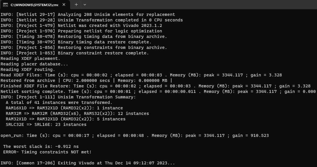
To meet the timing requirements for this design, you can use a slower clock for the AXI4-Lite interface and maintain the fast frequency for the DUT algorithm.
Integrate HDL IP Core into Reference Design with Two Different Frequencies
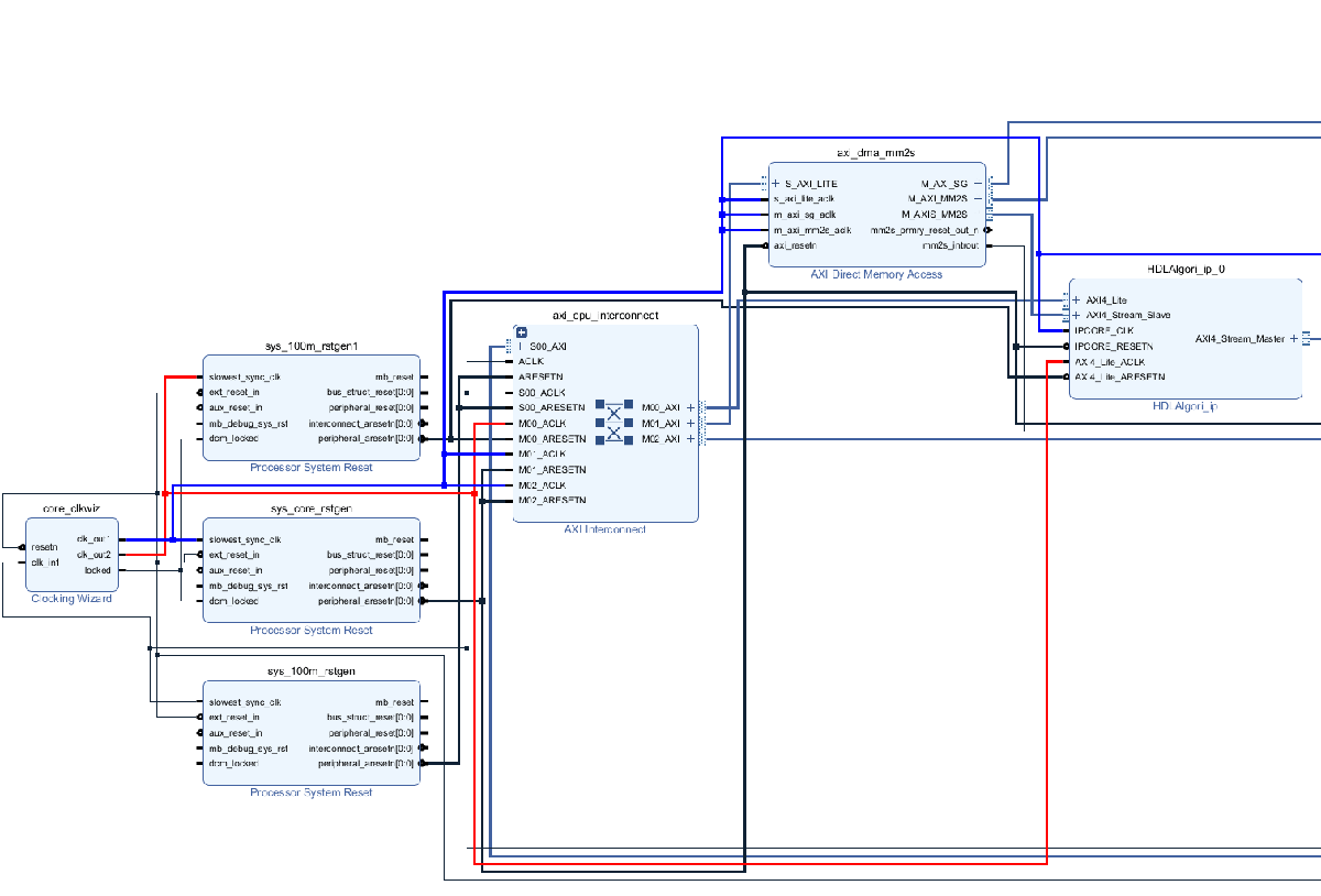
The FIR filter coefficients do not need to be updated at the same frequency as the data signal being filtered. Consequently, the AXI4-Lite interface can operate at a slower clock speed. In the reference design, connect the AXI4-Lite interface clock and the IP core clock to different clock sources, as shown in this image:
For this example, you use a custom reference design that connects the AXI4-Lite interface clock to a fixed 50 MHz clock, while the IP core clock is set to the value specified for the Target Frequency in the Configuration Parameters window. Specify the clock connection for the AXI4-Lite module when you add the register interface in the reference design plugin_rd.m file. The custom reference design in this example derives two different clocks from the same clock wizard. Because the first output, clk_out1, connects to the IPCORE_CLK, you can specify this connection when you add the clock interface. The second clock output, clk_out2, corresponds to a fixed 50 MHz clock which connects to the AXI4_Lite_ACLK, you can specify this connection when you add the AXI4 register interface. This code snippet specifies the clock and reset connections for the Default CDC system with AXI4-Stream Interface reference design.
%% Add interfaces
% add clock interface
hRD.addClockInterface( ...
    'ClockConnection',     'core_clkwiz/clk_out1', ...
    'ResetConnection',     'sys_core_rstgen/peripheral_aresetn',...
    'DefaultFrequencyMHz', 70,...
    'MinFrequencyMHz',     5,...
    'MaxFrequencyMHz',     500,...
    'ClockModuleInstance', 'core_clkwiz',...
    'ClockNumber',         1);

% add Register interfaces
hRD.addRegisterInterface( ...
    ... % Hardware (FPGA) properties
    'InterfaceConnection', 'axi_cpu_interconnect/M00_AXI', ...
    'BaseAddress',         '0x400D0000', ...
    'MasterAddressSpace',  'sys_cpu/Data', ...
     ...% Clock Connection
    'ClockConnection', 'core_clkwiz/clk_out2', ...
    'ResetConnection', 'sys_100m_rstgen1/peripheral_aresetn', ...
    ... % Software (Processor) properties
    'HasProcessorConnection', true, ...
    'DeviceTreeBusNode', '&fpga_axi');
To inspect the reference design files, open the HDL coder support package examples root directory. Open this directory by using this command:
cd(fullfile(hdlcoder_amd_examples_root,'ZedBoard'))
To configure the model to use CDC, add the reference design to your MATLAB® path by using:
addpath(genpath(fullfile(hdlcoder_amd_examples_root,'ZedBoard')))
Then configure the IP core:
Open the HDL Code Generation > Target tab of Configuration Parameters dialog box by clicking the Settings button.
Set the Reference Design parameter to
Default CDC system with AXI4-Stream Interfaceand click OK to save your updated settings.To enable the automatic insertion of the clock domain crossing logic between the AXI4-Stream interface and the DUT, in the HDL Code tab, click Target Interface to open the IP Core editor. Then in the Interface Settings tab, select Enable the clock domain crossing on AXI4-Lite registers.
After you configure the IP core settings, you can generate the bitstream. To check the Vivado® project:
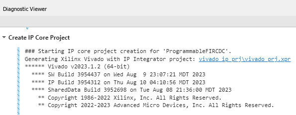
In the HDL Code tab, click Build Bitstream > Create IP Core Project. This action inserts the generated IP core into the Default CDC system with AXI4-Stream Interface reference design, which includes a clock wizard with two different outputs. The first output is the configurable clock for the IP core, which is highlighted in blue in the Vivado block design, and the second is fixed at 50 MHz for the AXI4-Lite interface, which is highlighted in red in the Vivado block design.
Click the link in the Diagnostic Viewer to open the generated Vivado project. In Vivado, click Open Block Design to view the Zynq® design diagram.
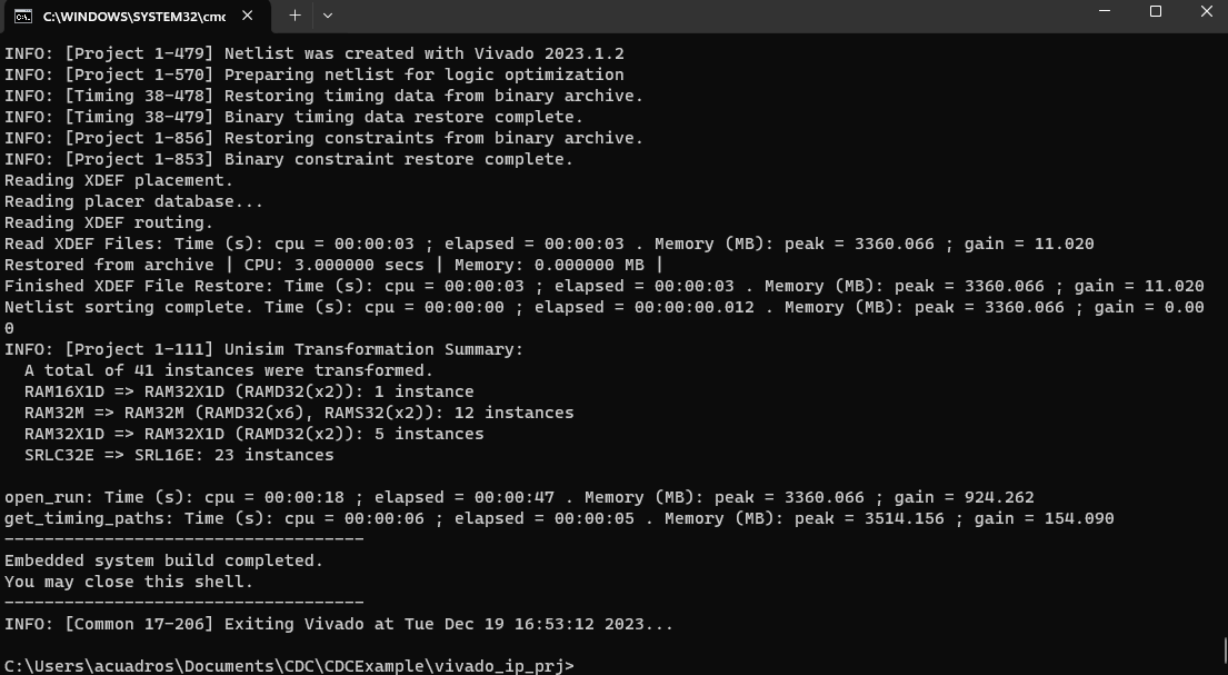
Alternatively, you can directly generate the bitstream. In the Simulink Toolstrip, in the HDL Code tab, click Build Bitstream and wait until the synthesis tool runs in the external window. The timing requirements are met after the modifications.
You can then use FPGA I/O API to prototype switching filter coefficients live on FPGA hardware. For more details, see Prototype Generated IP Core on Hardware using FPGA I/O
For more details regarding clock domain crossing in IP core generation, see Model Design for AXI4 Register Interface Generation.