Guided Hardware Setup for AMD Boards
You can use the Hardware Setup add-on to configure your target AMD® hardware board for the hardware-software co-design workflow. To set up the board, you load the MathWorks® firmware image onto an SD card, then use the Hardware Setup Add-On to configure the board, establish an Ethernet connection to the hardware, and set the hardware connections.
Prerequisites
Before starting the hardware setup, install the HDL Coder™ Support Package for AMD FPGA and SoC Devices. See Download and Install HDL Coder Support Package for AMD FPGA and SoC Devices.
Open the Hardware Setup tool
You can launch the Hardware Setup tool by following ways:
Using Add-Ons Panel
Start the Hardware Setup tool by opening the Add-Ons panel. Select Add-Ons > Manage Add-Ons.
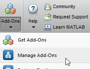
To launch the Hardware Setup tool, in the Add-Ons panel, point to required
support package and click the Settings button, ![]() .
.
Using hdlHardwareSetup Function
Start the Hardware Setup tool by using hdlHardwareSetup function. To open the Hardware Setup tool,
enter this command in MATLAB® command window:
hdlHardwareSetup
Using HDL Coder App
Start the Hardware Setup tool by using the HDL Coder app in Simulink®. To open the Hardware Setup tool from the Simulink toolstrip,
In the Simulink model, click Apps tab and select HDL Coder app.
On the Simulink toolstrip, select HDL Code tab. In the Output section, set the drop-down button to IP Core.
Open the HDL Code Generation > Target tab of Configuration Parameters dialog box by clicking the Settings button on the HDL Code tab. Select the required Target Platform. Click Ok.
In the HDL Code tab, click the drop-down button on the Build Bitstream and select Hardware Setup option.

Hardware Setup Workflow
To configure your SD card and hardware board, follow the instructions in each step of the Hardware Setup add-on.
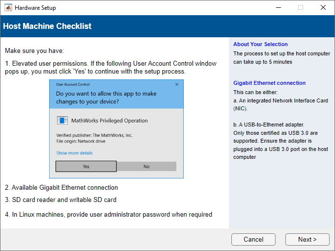
Host Machine Checklist
Because the software runs operating system commands to configure the network card, you may require administrator privileges to complete the hardware setup. To continue the setup process, provide your user permission when the User Account Control window opens. You can also start MATLAB using Run as administrator. In Linux® machines, provide the user administrator password when required.
This step also checks available Gigabit Ethernet connection, SD card reader, and writable SD card. Click Next to proceed.
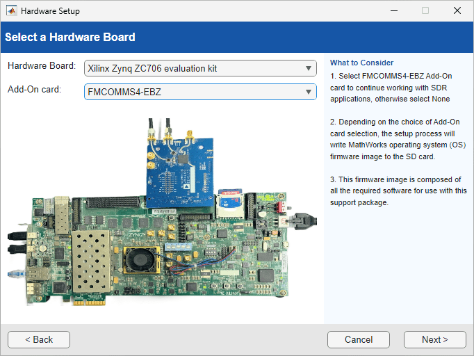
Select Hardware Board
Set the FPGA Vendor to AMD
(Xilinx) and choose your hardware from the list. The page
displays your selected hardware. For more information on the supported hardware,
see Supported EDA Tools and Hardware. Click Next.
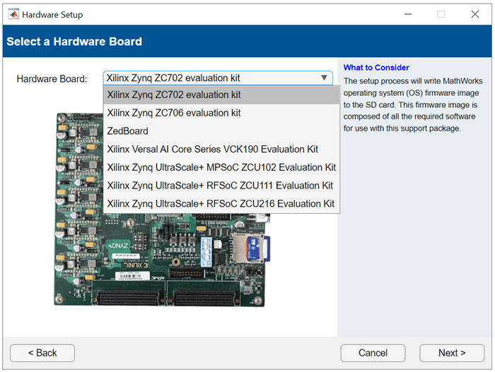
When you choose Xilinx Zynq ZC706 evaluation kit,
you can set the Add-on card to
FMCOMMS4-EBZ for software-defined radio (SDR)
applications.
When your board is not listed in the Hardware
Board option, you can set the Hardware Board to Custom
Board. For more information on how to set up the custom board,
see Set Up Custom Boards Using the Hardware Setup Add-On.
Download Required Third-Party Tools
You can automatically or manually download and install third-party tools for your board.
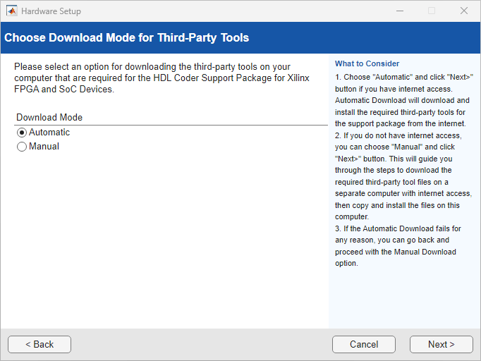
When you select Automatic, the wizard downloads and
installs the necessary third-party tools from the internet to your host
computer, which must have internet connectivity. After installation completes,
the third-party tools are available in the folder
support_package_installation_folder/3P.instrset/.
To get to the root folder of support packages, use the matlabshared.supportpkg.getSupportPackageRoot function.
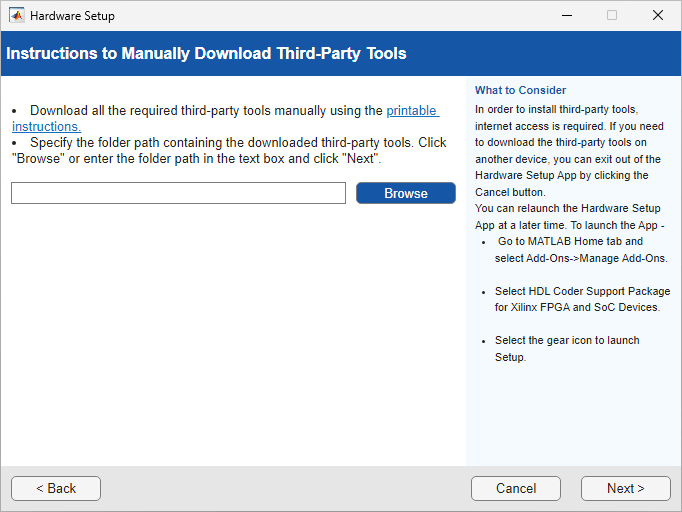
For host computers without internet access, you can select Manual to manually download the third-party tools. The wizard provides step-by-step instructions for downloading the required third-party tools. Use another computer with internet access to download these tools and then transfer them on your host computer. After transferring the required third-party tools to the host computer, specify the folder path that contains the third-party tools and click Next.
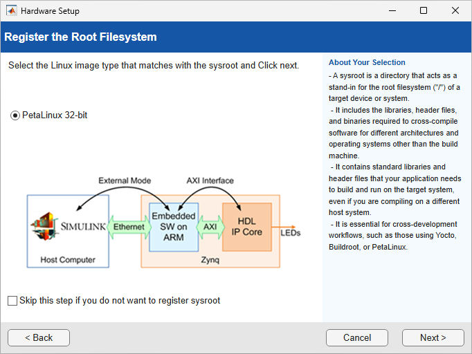
Register Root File System
This is step is required only if you use an Ethernet interface to connect to the target board and you installed third-party tools for software targeting in the Download and Install Third-Party Tools step.
On the Register the Root Filesystem step, you register the Linux root file system (sysroot) for the target AMD board. The sysroot provides the libraries, header files, and binaries required to cross‑compile, deploy, and run generated code on the target hardware. You must register a sysroot when using cross‑development workflows, such as those that use Yocto, Buildroot, or PetaLinux.
Select the Linux image type that matches the root file system installed on the target device:
PetaLinux 32‑bit — Select this option when the target device is running a 32‑bit PetaLinux image.
PetaLinux 64‑bit — Select this option when the target device is running a 64‑bit PetaLinux image.
If you do not want to register a sysroot, select the Skip this step if you do not want to register sysroot check box and click Next. You can register the sysroot later by using the Hardware Setup tool.
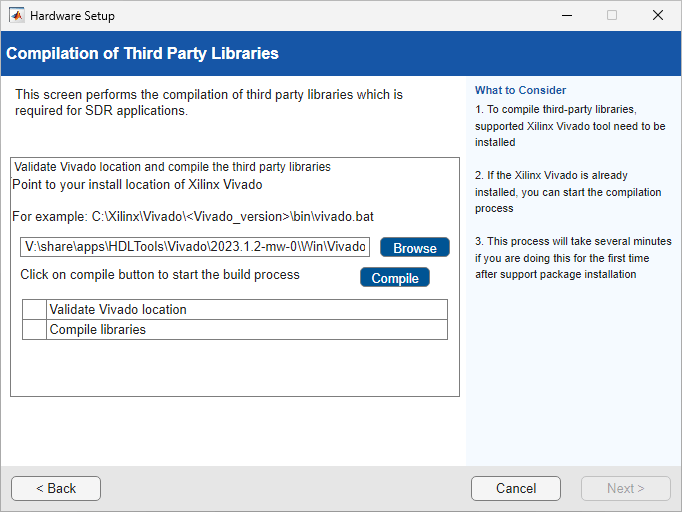
Compile Third-Party Tools for SDR Hardware
The Compilation of Third Party Libraries step appears
only when you select Hardware Board to Xilinx
Zynq ZC706 evaluation kit hardware for SDR applications.
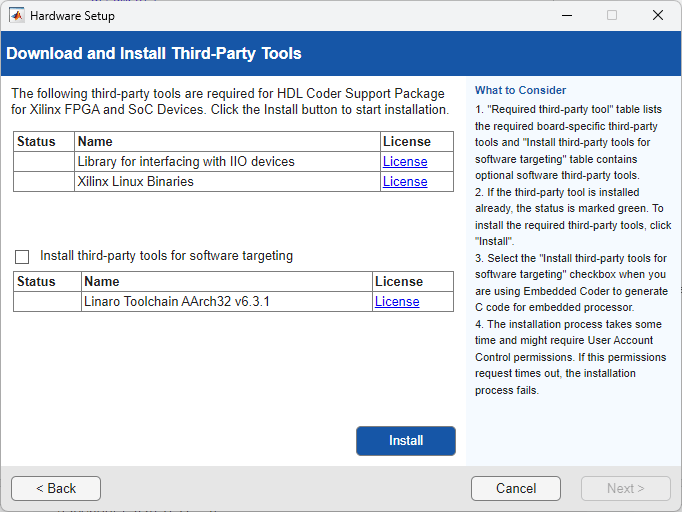
This step compiles these third-party libraries, which are required for SDR applications:
Analog Devices® Inc. HDL IP
Library for interfacing with IIO devices
Xilinx® Linux Binaries
To compile these libraries, provide the Xilinx
Vivado® synthesis tool path and click Compile. If you
have already set tool the path by using hdlsetuptoolpath function,
the tool path appears on the Browse field.
The compilation process takes several minutes to complete. After the process completes, click Next.
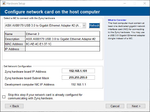
Configure Network Card on Host Computer
Select the network interface card (NIC) that you want to connect with the hardware. If you have already configured the NIC, select Skip this step if your network card is already configured for communicating with the hardware. If you do not see your NIC, click Refresh.
The list displays the connected network interface cards detected on your computer. The menu options note each NIC as
(In Use)or(Available). When the NIC is connected to a device and has an assigned IP, the installer marks the NIC as(In Use).If all the NICs listed are in use, free up a NIC for use with the hardware, and then click Refresh.
If the NIC list is empty, it is possible that the VMWare software, if present, is interfering with NIC detection. To get an accurate list of NICs on your computer, remove the VMWare. Alternatively, check if the missing NIC is disabled in the control panel. If it is disabled, enable it.
Optionally, specify an IP address for your board. Click Next. The software configures the NIC.
Select Drive Containing SD Card
In the Select a Drive step, the Hardware Setup add-on writes a firmware image to the SD card. This firmware image is included with the support package. The image includes the embedded software and the FPGA programming file that enables you to use the hardware as an I/O peripheral.
This step selects the location of the SD drive that contains the card. Before downloading the firmware image to the card, unlock the SD card. Keep the card unlocked while the card is in the card reader of the target board.
Insert a 4 GB or larger SD memory card into the memory card reader on the host computer. The card must be formatted with the FAT32 format. Select the appropriate drive from the list. Click Next.

If your host computer does not have access to an SD card reader, you can copy the firmware image to your SD card using a guest computer that has the HDL Coder Support Package for AMD FPGA and SoC Devices and the required third-party tools installed.
To copy the SD card image from the guest computer, locate the
../3P.instrset/xilinxlinuxbinaries.instrset. If you have
downloaded the required third-party tool using the automatic download mode, the
folder is available in the
support_package_installation_folder/3P.instrset/
folder. In the xilinxlinuxbinaries.instrset folder, look for
the SD card image for the respective board, extract the contents of the zip
file, and then copy the contents to your SD card. To get to the root folder of
the support packages, use the matlabshared.supportpkg.getSupportPackageRoot function.
If your SD card already has an appropriate MathWorks Linux image to configure the hardware, you can skip this step by selecting the Skip this step if your SD card is already configured with appropriate MathWorks Linux Image for hardware check box. When you select this check box, the Hardware Setup add-on skips the Write Firmware step and proceeds to the Set Jumper and Switch Setting for Boards step.
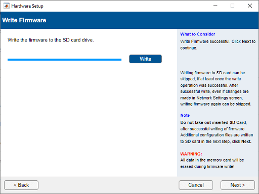
Write Firmware to SD Card
To copy the programming file from the host computer to the SD card, click Write. Any existing data on the memory card is erased during this process. When the write is complete, click Next.
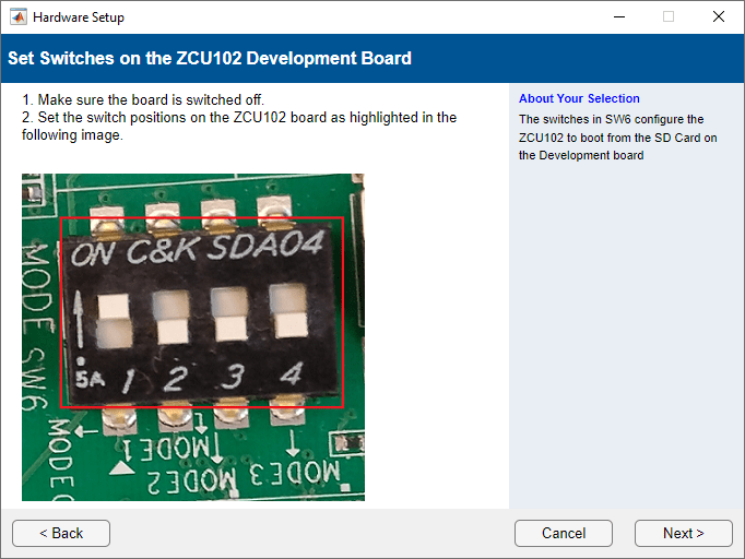
Set Jumper Switches for Hardware Board
Configure the jumpers switches on the selected hardware board so that you can use it as a peripheral device. The jumper settings are different for each board. This step guides you to use appropriate setting for development boards so that the board starts up from the SD card. When you set the jumper switch settings, make sure that the board is off.
For example, use these settings for the SW6 switch on the ZCU102 board.
SW6 Switch Positions on ZCU102
| Switch | 1 | 2 | 3 | 4 |
| Switch Position | Up | Down | Down | Down |
To know the jumper settings for the other supported boards, see Board-Specific Setup Information.
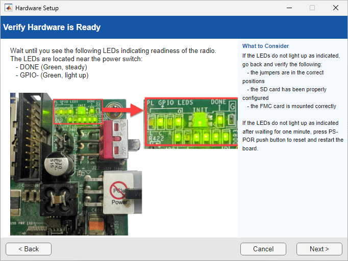
Connect the Hardware Board
Follow the instructions to connect the target hardware. Wait until the LEDs indicate that the hardware is ready. Then, wait an additional 20 seconds for the board to boot its operating system and set up communication with the host machine. The LEDs display a green, steady light when the board is ready. If the LEDs do not light up after one minute, press the reset switch and restart the board. Click Next. The software verifies the hardware connection.

When you select the Hardware Board to Xilinx
Zynq ZC706 evaluation kit hardware for SDR applications,
follow the instructions to set up board connections and click
Next. In the Verify Hardware is
Ready step, make sure that the LEDs light up as indicated.
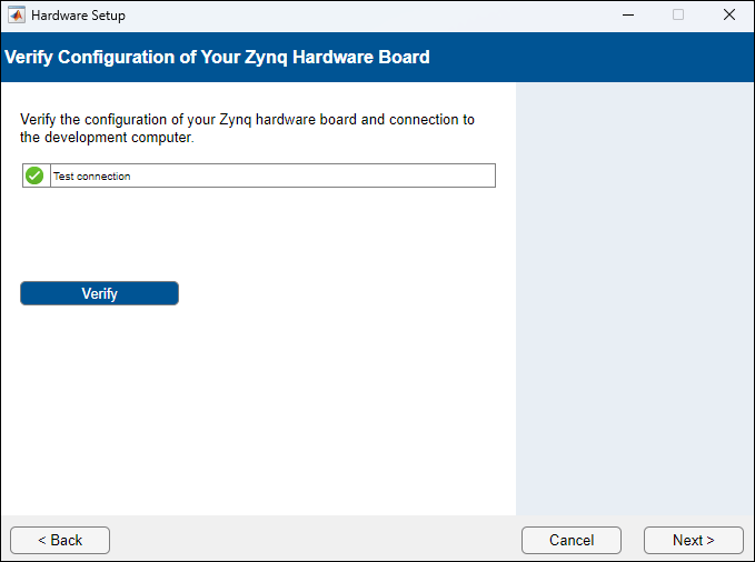
Verify Connection of Hardware Board
To verify the connection between the hardware board and your computer, click the Verify button and then click Next. After you verify the connection, you see a message that the hardware setup is complete.
You can skip this step if the connections to your board and development computer is already verified.
For RFSoC devices, see Check Connectivity of AMD RFSoC Boards.
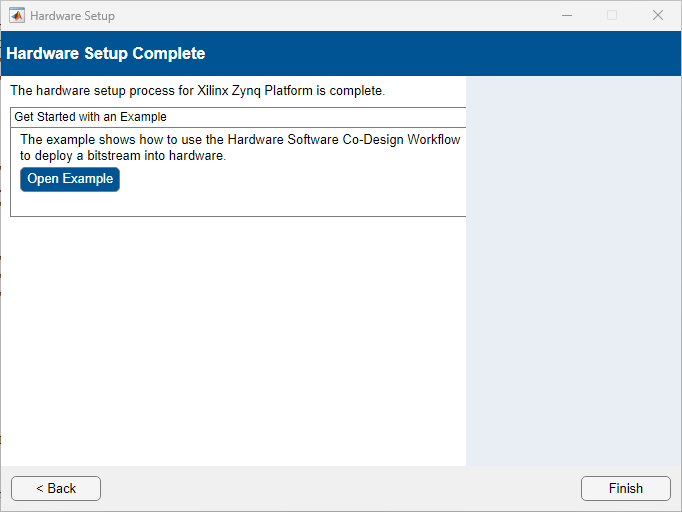
Launch Example
When the Hardware Setup completes, you can open the examples to get familiar with the product and its features. Click Open Example button to launch example in MATLAB which shows how to use Hardware Software Co-design workflow to deploy a bitstream into the hardware.