Generate SystemVerilog Assertions from Simulink Testbench
The DPI assertion block checks whether its input signal is zero. Use this block to check that your Simulink® testbench behaves as expected by creating a Boolean expression and connecting it to the block. Generating SystemVerilog creates an immediate assertion in your generated module. Use this block to check that your stimulus behaves as expected in both your Simulink and SystemVerilog environments.
Generate Assertions Workflow
This example shows how to create a model with an assertion block that emits a warning when the output of a gain block is zero. Then use a counter to display the model output.
Create a Simulink Model
The example model has a single gain block. This example creates a warning every time the gain output is zero.
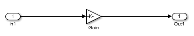
Open the Simulink Block Library > Commonly Used Blocks.
Add an Inport block.
Add a Gain block. Double-click this block to open its parameters. Set the value of Gain to
2.Add an Outport block.
Connect all blocks as shown in the preceding diagram.
Add and Configure Assertion Block
Find the Assertion block in the Libraries tree view by selecting HDL Verifier > For Use with DPI-C SystemVerilog. Add this block to your model, then connect the output of the Gain block to the input of the assertion block.
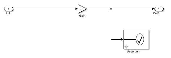
This example uses the Assertion block to monitor the Gain output and return a warning when the signal is zero. Double-click the Assertion block to configure its parameters. Set Severity to
warningand the Assertion fail message to"output is 0!". Make sure that Enable assertion is selected.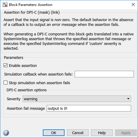
Note
The Parameters section control the Simulink execution, and they are identical to the parameters in the Simulink Assertion (Simulink) block. The DPI-C assertion options control the assertion behavior only in the generated SystemVerilog.
Customize the Assertion
Customize the assertion by setting Severity to
customand typing a custom SystemVerilog command in the Assertion custom command box. This command can include system tasks such as$displayor$time.You can further customize assertion behavior using the generated
DPI_getAssertionInfo(obj)SystemVerilog function. This function checks for executed assertions and returns all information recorded for that assertion in a SystemVerilog struct array. For each assertion that was executed in that clock cycle, the function returns theStatus,Message, andSeverityof the assertion.Run Simulation in Simulink
Before simulating, connect a stimulus source and a sink to your subsystem. This example uses a counter that generates 0-1-2-3 sequences.

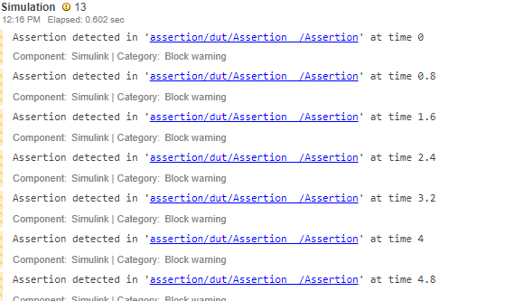
To build and run the simulation, click the Run button on toolbar.

Note the warnings from the assertion block in the output.
Generate SystemVerilog DPI Component
On the Simulink Apps tab click HDL Verifier. Then, on the HDL Verifier tab, click C Code Settings. The Configuration Parameters dialog box opens on Code Generation.
At System target file, click Browse and select
systemverilog_dpi_grt.tlc.If you have a license for Embedded Coder®, you can select target
systemverilog_dpi_ert.tlc. This target allows you to access its additional code generation options (on the Code Generation pane in Model Configuration Parameters).
In the Code Generation group, click SystemVerilog DPI.
To enable automatic testbench generation, select the Generate test bench check box.
Click OK to accept these settings and close the Configuration Parameters dialog box.
On the HDL Verifier tab, click Generate DPI Component.
The SystemVerilog component is generated as
dut_build/dut_dpi.svin your current working folder. In addition, a package file including function declarations is generated in asdut_build/dut_dpi_pkg.svin your current working folder.
Run the SystemVerilog Simulation
In the HDL Verifier tab click Select Simulator to open the Configuration Parameters on the SystemVerilog DPI pane. Then, select a simulator from the HDL simulator list. Click OK.
To start the simulator in GUI mode, expand the Run Testbench button and select Launch Simulator in GUI Mode.
For ModelSim™ or Questa™, enter the following command to start your simulation.
do run_tb_mq.do
Notice the simulation warnings displayed by the assertion:
run -all
# ** Warning: assertion:14:output is 0!
#    Time: 40 ns  Scope: dut_dpi_tb.u_dut_dpi File: ../dut_dpi.sv Line: 57
# ** Warning: assertion:14:output is 0!
#    Time: 80 ns  Scope: dut_dpi_tb.u_dut_dpi File: ../dut_dpi.sv Line: 57
# ** Warning: assertion:14:output is 0!
#    Time: 120 ns  Scope: dut_dpi_tb.u_dut_dpi File: ../dut_dpi.sv Line: 57
# ** Warning: assertion:14:output is 0!
#    Time: 160 ns  Scope: dut_dpi_tb.u_dut_dpi File: ../dut_dpi.sv Line: 57
# ** Warning: assertion:14:output is 0!
#    Time: 200 ns  Scope: dut_dpi_tb.u_dut_dpi File: ../dut_dpi.sv Line: 57
# ** Warning: assertion:14:output is 0!
#    Time: 240 ns  Scope: dut_dpi_tb.u_dut_dpi File: ../dut_dpi.sv Line: 57
# ** Warning: assertion:14:output is 0!
#    Time: 280 ns  Scope: dut_dpi_tb.u_dut_dpi File: ../dut_dpi.sv Line: 57
# ** Warning: assertion:14:output is 0!
#    Time: 320 ns  Scope: dut_dpi_tb.u_dut_dpi File: ../dut_dpi.sv Line: 57
# ** Warning: assertion:14:output is 0!
#    Time: 360 ns  Scope: dut_dpi_tb.u_dut_dpi File: ../dut_dpi.sv Line: 57
# ** Warning: assertion:14:output is 0!
#    Time: 400 ns  Scope: dut_dpi_tb.u_dut_dpi File: ../dut_dpi.sv Line: 57
# ** Warning: assertion:14:output is 0!
#    Time: 440 ns  Scope: dut_dpi_tb.u_dut_dpi File: ../dut_dpi.sv Line: 57
# ** Warning: assertion:14:output is 0!
#    Time: 480 ns  Scope: dut_dpi_tb.u_dut_dpi File: ../dut_dpi.sv Line: 57
# ** Warning: assertion:14:output is 0!
#    Time: 520 ns  Scope: dut_dpi_tb.u_dut_dpi File: ../dut_dpi.sv Line: 57
# **************TEST COMPLETED (PASSED)**************
# ** Note: $finish    : ./dut_dpi_tb.sv(62)
#    Time: 542 ns  Iteration: 0  Instance: /dut_dpi_tb
# End time: 14:16:43 on Dec 29,2017, Elapsed time: 0:00:04
# Errors: 0, Warnings: 13
Trace Generated SystemVerilog Assertions
After running a SystemVerilog simulation with a generated assertion, your log file displays warnings
and errors. To identify which assertion block originated a specific warning or error
output, use the hilite_system (Simulink) function.
Each warning displays a number identifying the specific Assertion block that generated that warning. That number is the Simulink identifier (SID) of that block. For example, the following shows a warning generated by assertion block with SID number 14.
# ** Warning: assertion:14:output is 0!
To highlight the block that generated this warning, execute the following code in your MATLAB® command window.
hilite_system('assertion:14')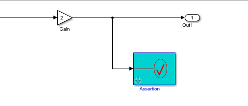
Disabling Assertions
You can disable any assertion block from executing either in your Simulink environment or in your SystemVerilog environment. Disable the assertion in Simulink if you want an assertion ignored both in Simulink and in SystemVerilog. Disable the assertion in SystemVerilog if you do not want to regenerate code from Simulink, but want the ability to disable assertions during a SystemVerilog simulation.
Disabling Assertions in Simulink. You can disable the DPI-C Assertion block from checking its input signal or emitting warnings or errors by clearing the Enable assertion check box in the Assertion block parameters.

Clearing this check box disables the assertion from emitting any warnings or errors and generating a SystemVerilog assertion.
Disabling Assertions in SystemVerilog. In the SystemVerilog environment, you can disable the assertion by providing a Simulink Identifier as a command-line argument to the HDL simulator. For example, when using ModelSim and assuming the SID is 14, you can disable the output of any warnings, error messages, or custom commands produced by the Assertion block with the following plus-argument:
vsim -c -voptargs=+acc -sv_lib ../dut_win64 work.dut_dpi_tb +assertion:14