Verify Standalone CTLE in Architectural, Behavioral, and Circuit Domains
This example simulates a continuous-time linear equalizer (CTLE) in several design domains, while keeping the underlying models in synchronization through tool automation. The Simulink® architectural model acts as a high-level specification of the desired analog circuit behavior. Using HDL Verifier™, export the standalone CTLE model into a SystemVerilog behavioral model. The exported model enables early digital control development for analog calibration before you design the analog circuit. A circuit implementation of the CTLE is characterized (offline) using analog simulations. The characterization results are then fed back into the architectural model. This converts the specification-based Simulink model into a circuit-representative model. Both specification and circuit-representative models of the CTLE are provided as part of this example. Use HDL Verifier to regenerate the SystemVerilog behavioral model. This model can be used for mixed-signal validation; turning the specification-based SystemVerilog model into a circuit-representative SystemVerilog model. This automation keeps the architectural, behavioral, and circuit models in synchronicity.
Introduction and Motivation
This example demonstrates a SystemVerilog behavioral export flow for a standalone SerDes Toolbox™ CTLE. The CTLE is a common analog block for both analog-based (Figure. 1(a)) and ADC-based SerDes (Figure. 1(b)). The CTLE is an analog high-pass filter that partially or fully equalizes for channel loss. It also conditions the signal obtained from the channel for the subsequent equalizer stages. Depending on the SerDes standard, the CTLE may be a tunable filter where you can set the attenuation of the low-frequency signal component using digital control. Implementations that support further CTLE tuning capabilities are also possible, with increased circuit complexity.
(a) 
(b) 
Figure. 1 – An analog-based SerDes receiver (a) consists of custom analog blocks (CTLE & VCO), mixed-signal blocks (DFE), and custom digital blocks (1:16 demultiplexer), and synthesized digital in the form of the CDR. An ADC-based SerDes receiver (b) consists of custom analog blocks (CTLE & VCO), mixed-signal blocks (ADC), custom digital blocks (4:64 demultiplexer), and synthesized digital (FFE, DFE, and CDR). In both cases the blocks work together to equalize channel losses and recover transmitted data. Both topologies use a CTLE to perform initial receiver-based channel equalization and input signal conditioning for subsequent equalization stages.
Behavioral SystemVerilog models find use in mixed-signal design as stand-ins for analog functionality during the development and testing of digital circuits that interact with analog circuits. Typically, these analog-behavioral models are manually coded by an analog or digital designer to reflect the behavior of the circuit, once the analog design is mature. Yet, for SerDes designs the desired behavior of the CTLE is determined ahead of analog circuit design start, in the form of analog design specifications, which are derived from high-level system models. Early access to analog behavioral models is a key enabler for a left-shift of the mixed-signal validation efforts.
In this example, we first generate a SystemVerilog model of a CTLE based on a standalone SerDes Toolbox CTLE Simulink model, which is configured to reflect the CTLE analog design specifications. We then demonstrate the equivalence in the CTLE model's open loop behavior using Simulink and Verilog simulations. Next, we show how the SystemVerilog model can aid in digital circuit design and validation. Finally, the Simulink CTLE is updated with measured analog circuit data and the resulting SystemVerilog model is reexported without changing the SystemVerilog export flow.
Generate DPI Behavioral Model from Simulink Model
Examine the Simulink Architectural Model
The Simulink specification-based CTLE model, spec_CTLE.slx, opens with the project.
openProject('standalone_ctle_proj');
open_system('spec_CTLE');
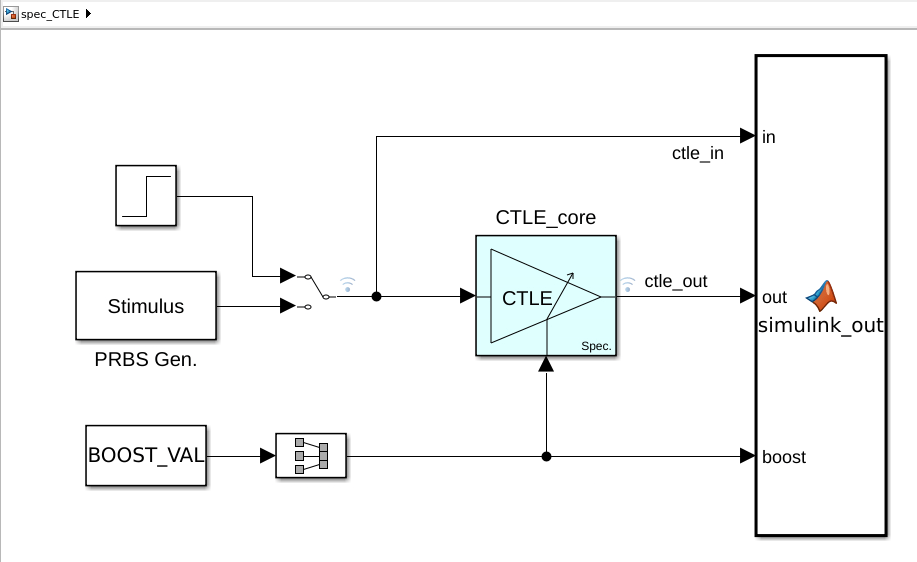
Figure. 2 – Simulink based CTLE testbench, where two input sources are provided to test the CTLE: a step response and a PRBS generator.
The Simulink model, shown in Figure. 2, consists of two manually selectable stimuli: a step input and a PRBS sequence generator. The CTLE model is a simplified version of a practical CTLE; thus, the specification-based CTLE model has only one control port to set the high-to-low-frequency (boost) gain.
open_system('spec_CTLE/CTLE_core')(a)  (b)
(b) 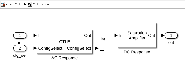
Figure. 3 – The (a) tunable CTLE is modeled using (b) an AC (small-signal) frequency-based response and a DC (large-signal) voltage-based response.
The specification-based high-frequency boost-only CTLE (Figure. 3(a)) is modeled using a series combination of a small-signal (AC) and large-signal (DC) response, as shown in Figure. 3(b) The frequency-domain behavior of the CTLE is captured by its AC response, which is encapsulated in the CTLE System object™. A saturation amplifier System object captures the DC response: large swing saturation (limiting).
Double click on the CTLE System object, this opens the CTLE dialog box, shown in Figure. 4(a). The specification-based CTLE is configured to have a peak gain at 20GHz, with a peak gain range of 0-20dB in 1dB steps, as shown by the magnitude/phase frequency responses in Figure. 4(b)
open_system('spec_CTLE/CTLE_core/AC Response')(a) 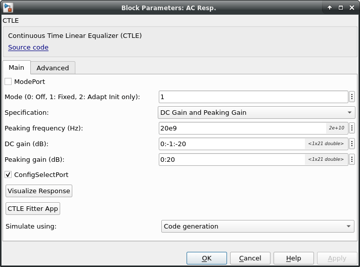 (b)
(b) 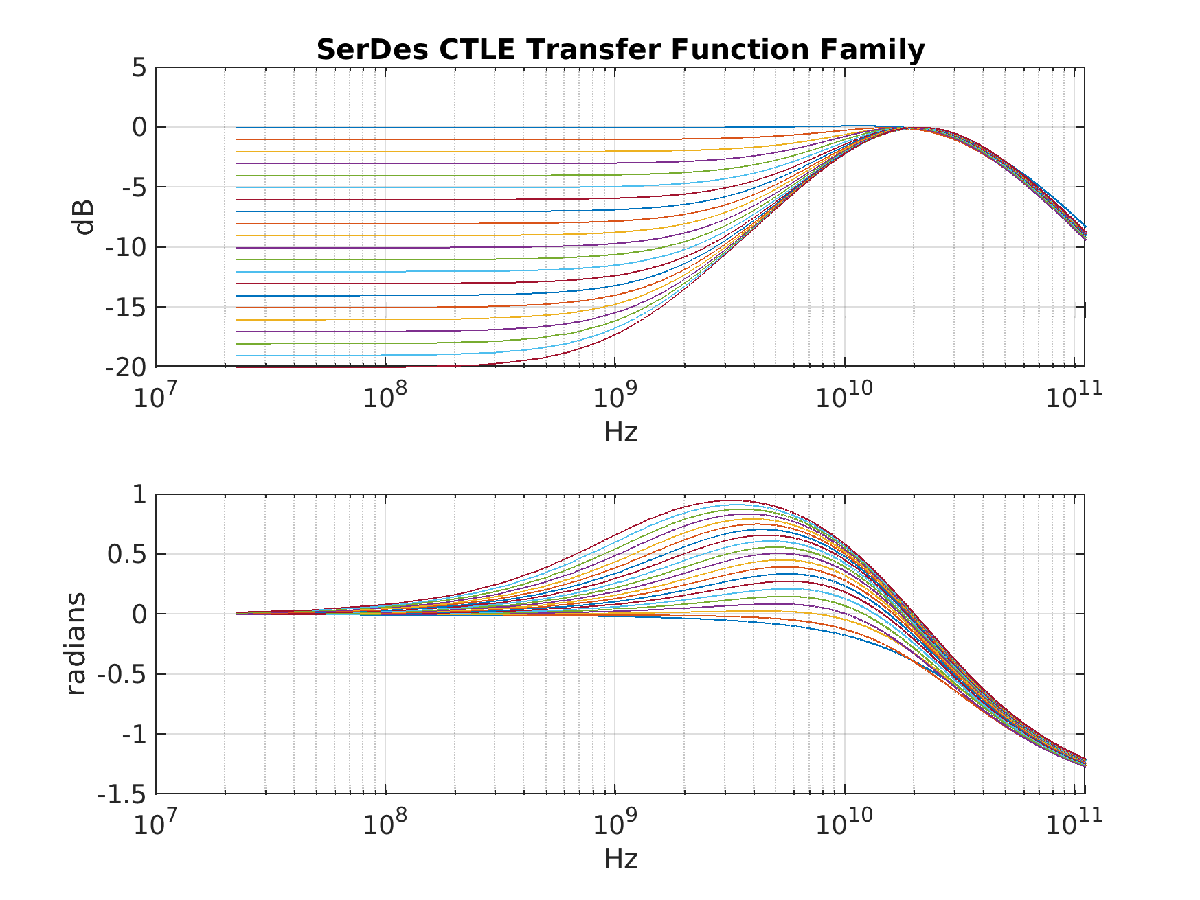
Figure. 4 – (a) SerDes Toolbox CTLE System object block parameter dialog box showing the configuration used for the specification-based CTLE model: 20GHz peaking frequency and peaking gain of 0 – 20dB in 1dB steps. (b) Frequency response curves for CTLE.
The large-signal DC response models the expected limited voltage swing of circuit elements, it is modeled using a Saturating Amplifier, with a pass-through gain of 1. Double click on the saturating amplifier, this brings up the dialog window shown in Figure. 5(a). The Saturating Amplifier is configured to have a gain of 1, and a voltage limit of +/- 0.4V. The resulting response can be visualized using the Visualize Response button and is shown in Figure. 5(b).
open_system('spec_CTLE/CTLE_core/DC Response')(a) 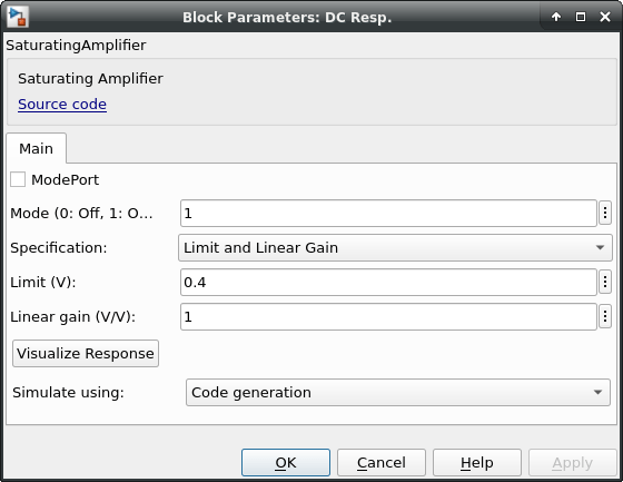 (b)
(b) 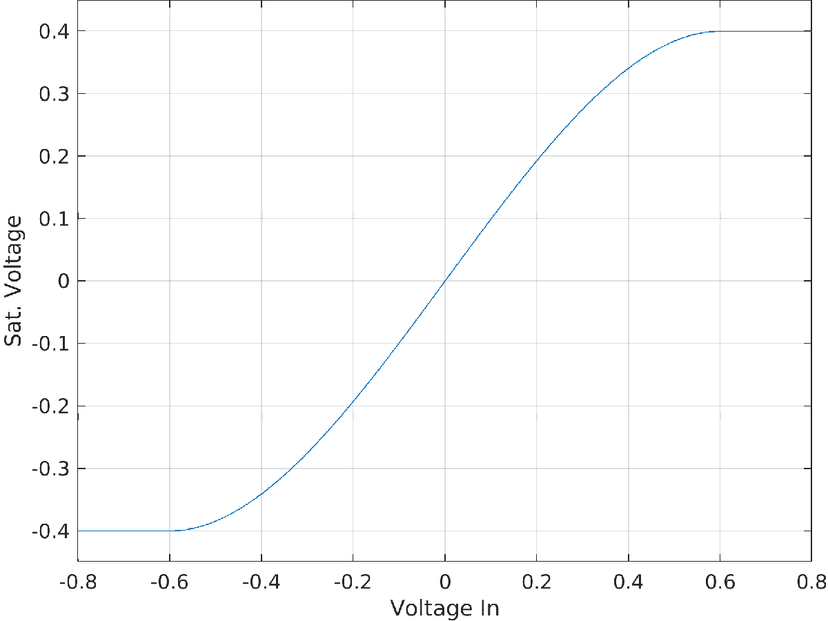
Figure. 5 – (a) SerDes Toolbox Saturating Amplifier System object block parameter dialog box showing the configuration used for the specification-based CTLE model: linear input swing limited to 0.4VPEAK. (b) Voltage input/output transfer characteristics for Saturating Amplifier, which shows the compression curve and swing limited to -0.4 to +0.4V.
Simulate the Architectural Model with Different Boost Values
Simulate the CTLE boost response in Simulink using the provided script ctle_run_sl_sims. Figure. 6a and Figure. 6b show the expected outputs for a step and PRBS sequence using boost settings of 0, 10, and 19 which corresponds to 0, 10dB, and 19dB of high-frequency boost. Note that for the larger boost settings the low frequency components of the input step are severely attenuated, as expected.
% First, choose the model to simulate
current_model = 'spec_CTLE' %#ok<*NASGU>
current_model =
'spec_CTLE'
% Run sim and plot results using step source
ctle_run_sl_sims
ctle_plot_sl_sims
Figure. 6a – Captured step input and output waveforms for CTLE configured for different boost settings: 0, 10, and 19dB DC attenuation.
Change the signal source to PRBS and rerun.
% Change source to a pseudorandom binary sequence and rerun and replot
open_system('spec_CTLE/input_switch') % toggle to PRBS
ctle_run_sl_sims
ctle_plot_sl_sims

Figure. 6b – Captured PRBS input and output waveforms for CTLE configured for different boost settings.
Export the CTLE to a SystemVerilog Behavioral Model
Create a SystemVerilog view of the CTLE model using the provided, preconfigured, and export-ready Simulink model by selecting the CTLE_core model in the Simulink model shown in Figure. 2. Then, open the HDL Verifier tab, and push the Generate DPI Component button, as shown below.

Alternatively, use the command line to generate the DPI component.
% Build a SystemVerilog DPI component from the CTLE_core subsystem.
slbuild('spec_CTLE/CTLE_core')
### Searching for referenced models in model 'CTLE_core'.
### Total of 1 models to build.
### Starting build procedure for model: CTLE_core
### Starting SystemVerilog DPI Component Generation
### Generating DPI H Wrapper CTLE_core_dpi.h
### Generating DPI-C Wrapper CTLE_core_dpi.c
### Generating SystemVerilog module CTLE_core_dpi.sv using template Z:\50\hagam.Bmain.j2746022\matlab\toolbox\hdlverifier\dpigenerator\rtw\svdpi_event.vgt.
### Generating makefiles for: CTLE_core_dpi
### Invoking make to build the DPI Shared Library
### Successful completion of build procedure for model: CTLE_core

Build Summary

Top model targets:

Model      Build Reason                     Status                        Build Duration
========================================================================================
CTLE_core  Generated code was out of date.  Code generated and compiled.  0h 1m 58.637s

1 of 1 models built (0 models already up to date)
Build duration: 0h 2m 3.6523s
See Get Started with MATLAB Based SystemVerilog DPI Generation and Get Started with SystemVerilog DPI Component Generation for further information how to configure a MATLAB® or Simulink based model for System Verilog export.
An analog CTLE is likely to be implemented using a differential circuit; therefore, the inputs and outputs to the CTLE are differential signals, yet the architectural model will have likely abstracted the differential nature of the circuit as the Simulink CTLE model does, other than accounting for the voltage-headroom limited differential swing via the saturating amplifier. Moreover, the analog CTLE implementation may also incorporate calibration circuits, such as input offset compensation.
Hence, the exported Simulink (architectural) model serves as the core of a complete CTLE behavioural model. Differential to single-ended and single-ended to differential conversion is needed before and after the architectural model core (blue box) to provide input/output format conversion. This is performed within the provided Verilog CTLE behavioral model wrapper, hdl_rtl/ctle.v. The CTLE behavioral model also allows one to control the amount of input-referred noise to be applied.
Finite input offset is unavoidable in differential analog circuits and needs to be compensated after manufacturing. A simple input-offset compensation circuit is shown in feedback around the architectural core model in Figure. 7. It consists of a clocked comparator, a digital calibration engine, and a digital-to-analog converter (DAC).
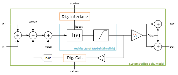
Figure. 7 – Block diagram for SystemVerilog CTLE Behavioral model, where the core analog functionality (blue box) is directly exported from the architectural Simulink model. A reusable SystemVerilog harness (green box) provides the behavioral-to-architectural model interface, while also pulling in additional support systems not present, nor required, in the architectural model: the clocked comparator, digital calibration engine, and DAC.
The digital calibration engine, for which a block diagram is shown in Figure. 8, is implemented using RTL Verilog and provided as part of the example in hdl_rtl/ctle_cm_cal.v.
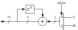
Figure. 8 - Digital offset calibration engine. When enabled, the sampled (high/low) CTLE differential output is digitally integrated using an N-bit up/down counter. The upper M bits of the counter are used to drive a DAC, which provides a constant DC offset into the CTLE; thereby, compensating for its intrinsic offset.
Simulate the Behavioral Model in SystemVerilog
To run a suite of tests for boost settings 0, 10, and 19dB, use the provided ctle_run_cases script. This script first runs a Simulink simulation using a BOOST_VAL setting, storing the input and output data into a BOOST_VAL indexed log file. Then, a Verilog simulation is run using the same BOOST_VAL setting. The Verilog simulation reads in the input waveform used for the Simulink simulation and applies it to the SystemVerilog model in the Verilog simulator. The provided CTLE testbench also creates a text log file of the Verilog simulation run: the files are named depending on the boost setting used (e.g. verilog_out_b00.log for BOOST_VAL=0). Note that the data is logged at the green box, see Figure. 7, boundary; hence, the individual single ended signals are stored. The contents of this file can be read back into the MATLAB environment and plotted against the accompanying Simulink output using the ctle_plot_cases script. Note that one can also visualize a generated, standard VCD file of the Verilog results outside of MATLAB, for example using GTKWaves.
The run script supports different HDL simulators. You must set up your path and other environment for your simulator.
% This is a MathWorks-specific setup. You must assign PATH and
% other settings specific to your environment for your chosen simulator.
setup_questa();
Choose an HDL Simulator
% Uncomment one of the following supported HDL simulator choices:
current_hdl_simulator = 'Questa'; % Windows or Linux
% current_hdl_simulator = 'Xcelium'; % Linux only
% current_hdl_simulator = 'VCS'; % Linux only
% current_hdl_simulator = 'Vivado'; % Linux only
% Run Simulink and HDL sim and plot results comparison
ctle_run_cases
Reading pref.tcl
# 2022.2
# do {scripts\ctle_tb_tran_questa.do}
# 0
# Environment BOOST_VAL=0
# ** Warning: (vlib-34) Library already exists at "work".
# Errors: 0, Warnings: 1
# QuestaSim-64 vlog 2022.2 Compiler 2022.04 Apr 25 2022
# Start time: 10:40:42 on Oct 01,2024
# vlog -sv CTLE_core_build/CTLE_core_dpi.sv
# -- Compiling module CTLE_core_dpi
#
# Top level modules:
# CTLE_core_dpi
# End time: 10:40:43 on Oct 01,2024, Elapsed time: 0:00:01
# Errors: 0, Warnings: 0
# QuestaSim-64 vlog 2022.2 Compiler 2022.04 Apr 25 2022
# Start time: 10:40:44 on Oct 01,2024
# vlog -sv hdl_rtl/ctle_cm_cal.v hdl_rtl/ctle.v hdl_tb/ctle_tb_tran.v
# -- Compiling module ctle_cm_cal
# -- Compiling module ctle
# -- Compiling module ctle_tb_tran
#
# Top level modules:
# ctle_tb_tran
# End time: 10:40:46 on Oct 01,2024, Elapsed time: 0:00:02
# Errors: 0, Warnings: 0
# vsim -c -sv_lib CTLE_core_build/CTLE_core_win64 work.ctle_tb_tran "+BOOST_VAL=0"
# Start time: 10:40:47 on Oct 01,2024
# ** Note: (vsim-8009) Loading existing optimized design _opt
# // Questa Sim-64
# // Version 2022.2 win64 Apr 25 2022
# //
# // Copyright 1991-2022 Mentor Graphics Corporation
# // All Rights Reserved.
# //
# // QuestaSim and its associated documentation contain trade
# // secrets and commercial or financial information that are the property of
# // Mentor Graphics Corporation and are privileged, confidential,
# // and exempt from disclosure under the Freedom of Information Act,
# // 5 U.S.C. Section 552. Furthermore, this information
# // is prohibited from disclosure under the Trade Secrets Act,
# // 18 U.S.C. Section 1905.
# //
# Loading sv_std.std
# Loading work.ctle_tb_tran(fast)
# Loading .\CTLE_core_build/CTLE_core_win64.dll
# CTLE_TB_TRAN: Running with boost = 0
# ** Note: $finish : hdl_tb/ctle_tb_tran.v(52)
# Time: 10000476 fs Iteration: 0 Instance: /ctle_tb_tran
# End time: 10:40:51 on Oct 01,2024, Elapsed time: 0:00:04
# Errors: 0, Warnings: 0
Reading pref.tcl
# 2022.2
# do {scripts\ctle_tb_tran_questa.do}
# 10
# Environment BOOST_VAL=10
# ** Warning: (vlib-34) Library already exists at "work".
# Errors: 0, Warnings: 1
# QuestaSim-64 vlog 2022.2 Compiler 2022.04 Apr 25 2022
# Start time: 10:41:08 on Oct 01,2024
# vlog -sv CTLE_core_build/CTLE_core_dpi.sv
# -- Compiling module CTLE_core_dpi
#
# Top level modules:
# CTLE_core_dpi
# End time: 10:41:09 on Oct 01,2024, Elapsed time: 0:00:01
# Errors: 0, Warnings: 0
# QuestaSim-64 vlog 2022.2 Compiler 2022.04 Apr 25 2022
# Start time: 10:41:09 on Oct 01,2024
# vlog -sv hdl_rtl/ctle_cm_cal.v hdl_rtl/ctle.v hdl_tb/ctle_tb_tran.v
# -- Compiling module ctle_cm_cal
# -- Compiling module ctle
# -- Compiling module ctle_tb_tran
#
# Top level modules:
# ctle_tb_tran
# End time: 10:41:11 on Oct 01,2024, Elapsed time: 0:00:02
# Errors: 0, Warnings: 0
# vsim -c -sv_lib CTLE_core_build/CTLE_core_win64 work.ctle_tb_tran "+BOOST_VAL=10"
# Start time: 10:41:12 on Oct 01,2024
# ** Note: (vsim-8009) Loading existing optimized design _opt
# // Questa Sim-64
# // Version 2022.2 win64 Apr 25 2022
# //
# // Copyright 1991-2022 Mentor Graphics Corporation
# // All Rights Reserved.
# //
# // QuestaSim and its associated documentation contain trade
# // secrets and commercial or financial information that are the property of
# // Mentor Graphics Corporation and are privileged, confidential,
# // and exempt from disclosure under the Freedom of Information Act,
# // 5 U.S.C. Section 552. Furthermore, this information
# // is prohibited from disclosure under the Trade Secrets Act,
# // 18 U.S.C. Section 1905.
# //
# Loading sv_std.std
# Loading work.ctle_tb_tran(fast)
# Loading .\CTLE_core_build/CTLE_core_win64.dll
# CTLE_TB_TRAN: Running with boost = 10
# ** Note: $finish : hdl_tb/ctle_tb_tran.v(52)
# Time: 10000476 fs Iteration: 0 Instance: /ctle_tb_tran
# End time: 10:41:15 on Oct 01,2024, Elapsed time: 0:00:03
# Errors: 0, Warnings: 0
Reading pref.tcl
# 2022.2
# do {scripts\ctle_tb_tran_questa.do}
# 19
# Environment BOOST_VAL=19
# ** Warning: (vlib-34) Library already exists at "work".
# Errors: 0, Warnings: 1
# QuestaSim-64 vlog 2022.2 Compiler 2022.04 Apr 25 2022
# Start time: 10:41:33 on Oct 01,2024
# vlog -sv CTLE_core_build/CTLE_core_dpi.sv
# -- Compiling module CTLE_core_dpi
#
# Top level modules:
# CTLE_core_dpi
# End time: 10:41:34 on Oct 01,2024, Elapsed time: 0:00:01
# Errors: 0, Warnings: 0
# QuestaSim-64 vlog 2022.2 Compiler 2022.04 Apr 25 2022
# Start time: 10:41:34 on Oct 01,2024
# vlog -sv hdl_rtl/ctle_cm_cal.v hdl_rtl/ctle.v hdl_tb/ctle_tb_tran.v
# -- Compiling module ctle_cm_cal
# -- Compiling module ctle
# -- Compiling module ctle_tb_tran
#
# Top level modules:
# ctle_tb_tran
# End time: 10:41:36 on Oct 01,2024, Elapsed time: 0:00:02
# Errors: 0, Warnings: 0
# vsim -c -sv_lib CTLE_core_build/CTLE_core_win64 work.ctle_tb_tran "+BOOST_VAL=19"
# Start time: 10:41:37 on Oct 01,2024
# ** Note: (vsim-8009) Loading existing optimized design _opt
# // Questa Sim-64
# // Version 2022.2 win64 Apr 25 2022
# //
# // Copyright 1991-2022 Mentor Graphics Corporation
# // All Rights Reserved.
# //
# // QuestaSim and its associated documentation contain trade
# // secrets and commercial or financial information that are the property of
# // Mentor Graphics Corporation and are privileged, confidential,
# // and exempt from disclosure under the Freedom of Information Act,
# // 5 U.S.C. Section 552. Furthermore, this information
# // is prohibited from disclosure under the Trade Secrets Act,
# // 18 U.S.C. Section 1905.
# //
# Loading sv_std.std
# Loading work.ctle_tb_tran(fast)
# Loading .\CTLE_core_build/CTLE_core_win64.dll
# CTLE_TB_TRAN: Running with boost = 19
# ** Note: $finish : hdl_tb/ctle_tb_tran.v(52)
# Time: 10000476 fs Iteration: 0 Instance: /ctle_tb_tran
# End time: 10:41:40 on Oct 01,2024, Elapsed time: 0:00:03
# Errors: 0, Warnings: 0
ctle_plot_cases

Figure. 10 – Comparison of Simulink and Verilog CTLE output waveforms for various boost values.
Verify Closed-Loop Behavior in Verilog
Thus far, this example has shown that the open-loop (through path) behavior of the CTLE behavioral model in Simulink and Verilog matches. However, as implied by Figure. 7 the behavioral CTLE model shows strength in being used to develop and test mixed-signal systems, specifically digital subsystems and their interaction with analog systems in a closed loop.
We have already discussed the non-zero input referred offset that is expected for a practical CTLE implementation, and the required offset calibration circuit needed to remove the random input-referred offset. In this section we use the behavioral model of the CTLE to validate the functionality of the digital offset calibration engine, shown in Figure. 8. This calibration engine is in a closed loop with a clocked comparator and DAC as shown in Figure. 7. Both the clocked-comparator and DAC are modeled inline within the provided CTLE Verilog behavioral model (hdl_rtl/ctle.v); however, these blocks could also be modelled as exported SystemVerilog analog behavioral models using the flow described in this example. Whereas, the digital controller, shown in Figure. 8, is implemented using synthesizable RTL, which is provided by hdl_rtl/ctle_cm_cal.v.
% Open these Verilog source files in the editor for examination.
edit hdl_tb/ctle_tb_offcomp.v
edit hdl_rtl/ctle.v
edit hdl_rtl/ctle_cm_cal.v
1. Review the offset compensator testbench, hdl_tb/ctle_tb_offcomp.v, and note that
The CTLE inputs (inp and inm) are tied to the common mode (cm), thereby providing a 0V differential input.
The common mode calibration block is enabled (cm_cal_en) shortly after reset
An asynchronous clock generator, whose frequency can be configured by the async_freq parameter, generates the clock for the digital calibration engine and the clocked-comparator. Note that offset is a DC characteristic, so there is no specific frequency constraint on the sampling clock, other than time required to complete calibration
2. Inspect the CTLE offset calibration engine, hdl_rtl/ctle_cm_cal.v and study how it is used within hdl_rtl/ctle.v. Do you see any implementation issues?
3. Simulate the CTLE offset compensation testbench using 3 different predefined settings for CTLE boost using the ctle_run_offset_cals script.
4. Plot the resulting logged waveforms for the simulation run using the ctle_plot_offset_cals script. The resulting waveforms are shown below in Figure. 12. Note that the Verilog testbench also generates a VCD file that can be inspected inside using standard digital debugging tools.
% Run offset calibration Verilog testbench and plot results in MATLAB
ctle_run_offset_cals
Reading pref.tcl
# 2022.2
# do {scripts\ctle_tb_offcomp_questa.do}
# 0
# Environment BOOST_VAL=0
# ** Warning: (vlib-34) Library already exists at "work".
# Errors: 0, Warnings: 1
# QuestaSim-64 vlog 2022.2 Compiler 2022.04 Apr 25 2022
# Start time: 10:41:57 on Oct 01,2024
# vlog -sv CTLE_core_build/CTLE_core_dpi.sv
# -- Compiling module CTLE_core_dpi
#
# Top level modules:
# CTLE_core_dpi
# End time: 10:41:58 on Oct 01,2024, Elapsed time: 0:00:01
# Errors: 0, Warnings: 0
# QuestaSim-64 vlog 2022.2 Compiler 2022.04 Apr 25 2022
# Start time: 10:41:59 on Oct 01,2024
# vlog -sv hdl_rtl/ctle_cm_cal.v hdl_rtl/ctle.v hdl_tb/ctle_tb_offcomp.v
# -- Compiling module ctle_cm_cal
# -- Compiling module ctle
# -- Compiling module ctle_tb_offcomp
#
# Top level modules:
# ctle_tb_offcomp
# End time: 10:42:01 on Oct 01,2024, Elapsed time: 0:00:02
# Errors: 0, Warnings: 0
# vsim -c -sv_lib CTLE_core_build/CTLE_core_win64 work.ctle_tb_offcomp "+BOOST_VAL=0"
# Start time: 10:42:02 on Oct 01,2024
# ** Note: (vsim-8009) Loading existing optimized design _opt1
# // Questa Sim-64
# // Version 2022.2 win64 Apr 25 2022
# //
# // Copyright 1991-2022 Mentor Graphics Corporation
# // All Rights Reserved.
# //
# // QuestaSim and its associated documentation contain trade
# // secrets and commercial or financial information that are the property of
# // Mentor Graphics Corporation and are privileged, confidential,
# // and exempt from disclosure under the Freedom of Information Act,
# // 5 U.S.C. Section 552. Furthermore, this information
# // is prohibited from disclosure under the Trade Secrets Act,
# // 18 U.S.C. Section 1905.
# //
# Loading sv_std.std
# Loading work.ctle_tb_offcomp(fast)
# Loading .\CTLE_core_build/CTLE_core_win64.dll
# CTLE_TB_OFFCOMP: Running with boost = 0
# ** Note: $finish : hdl_tb/ctle_tb_offcomp.v(46)
# Time: 750 ns Iteration: 1 Instance: /ctle_tb_offcomp
# End time: 10:42:14 on Oct 01,2024, Elapsed time: 0:00:12
# Errors: 0, Warnings: 0
Reading pref.tcl
# 2022.2
# do {scripts\ctle_tb_offcomp_questa.do}
# 10
# Environment BOOST_VAL=10
# ** Warning: (vlib-34) Library already exists at "work".
# Errors: 0, Warnings: 1
# QuestaSim-64 vlog 2022.2 Compiler 2022.04 Apr 25 2022
# Start time: 10:42:27 on Oct 01,2024
# vlog -sv CTLE_core_build/CTLE_core_dpi.sv
# -- Compiling module CTLE_core_dpi
#
# Top level modules:
# CTLE_core_dpi
# End time: 10:42:28 on Oct 01,2024, Elapsed time: 0:00:01
# Errors: 0, Warnings: 0
# QuestaSim-64 vlog 2022.2 Compiler 2022.04 Apr 25 2022
# Start time: 10:42:29 on Oct 01,2024
# vlog -sv hdl_rtl/ctle_cm_cal.v hdl_rtl/ctle.v hdl_tb/ctle_tb_offcomp.v
# -- Compiling module ctle_cm_cal
# -- Compiling module ctle
# -- Compiling module ctle_tb_offcomp
#
# Top level modules:
# ctle_tb_offcomp
# End time: 10:42:30 on Oct 01,2024, Elapsed time: 0:00:01
# Errors: 0, Warnings: 0
# vsim -c -sv_lib CTLE_core_build/CTLE_core_win64 work.ctle_tb_offcomp "+BOOST_VAL=10"
# Start time: 10:42:31 on Oct 01,2024
# ** Note: (vsim-8009) Loading existing optimized design _opt1
# // Questa Sim-64
# // Version 2022.2 win64 Apr 25 2022
# //
# // Copyright 1991-2022 Mentor Graphics Corporation
# // All Rights Reserved.
# //
# // QuestaSim and its associated documentation contain trade
# // secrets and commercial or financial information that are the property of
# // Mentor Graphics Corporation and are privileged, confidential,
# // and exempt from disclosure under the Freedom of Information Act,
# // 5 U.S.C. Section 552. Furthermore, this information
# // is prohibited from disclosure under the Trade Secrets Act,
# // 18 U.S.C. Section 1905.
# //
# Loading sv_std.std
# Loading work.ctle_tb_offcomp(fast)
# Loading .\CTLE_core_build/CTLE_core_win64.dll
# CTLE_TB_OFFCOMP: Running with boost = 10
# ** Note: $finish : hdl_tb/ctle_tb_offcomp.v(46)
# Time: 750 ns Iteration: 1 Instance: /ctle_tb_offcomp
# End time: 10:42:42 on Oct 01,2024, Elapsed time: 0:00:11
# Errors: 0, Warnings: 0
Reading pref.tcl
# 2022.2
# do {scripts\ctle_tb_offcomp_questa.do}
# 19
# Environment BOOST_VAL=19
# ** Warning: (vlib-34) Library already exists at "work".
# Errors: 0, Warnings: 1
# QuestaSim-64 vlog 2022.2 Compiler 2022.04 Apr 25 2022
# Start time: 10:42:54 on Oct 01,2024
# vlog -sv CTLE_core_build/CTLE_core_dpi.sv
# -- Compiling module CTLE_core_dpi
#
# Top level modules:
# CTLE_core_dpi
# End time: 10:42:55 on Oct 01,2024, Elapsed time: 0:00:01
# Errors: 0, Warnings: 0
# QuestaSim-64 vlog 2022.2 Compiler 2022.04 Apr 25 2022
# Start time: 10:42:56 on Oct 01,2024
# vlog -sv hdl_rtl/ctle_cm_cal.v hdl_rtl/ctle.v hdl_tb/ctle_tb_offcomp.v
# -- Compiling module ctle_cm_cal
# -- Compiling module ctle
# -- Compiling module ctle_tb_offcomp
#
# Top level modules:
# ctle_tb_offcomp
# End time: 10:42:57 on Oct 01,2024, Elapsed time: 0:00:01
# Errors: 0, Warnings: 0
# vsim -c -sv_lib CTLE_core_build/CTLE_core_win64 work.ctle_tb_offcomp "+BOOST_VAL=19"
# Start time: 10:42:59 on Oct 01,2024
# ** Note: (vsim-8009) Loading existing optimized design _opt1
# // Questa Sim-64
# // Version 2022.2 win64 Apr 25 2022
# //
# // Copyright 1991-2022 Mentor Graphics Corporation
# // All Rights Reserved.
# //
# // QuestaSim and its associated documentation contain trade
# // secrets and commercial or financial information that are the property of
# // Mentor Graphics Corporation and are privileged, confidential,
# // and exempt from disclosure under the Freedom of Information Act,
# // 5 U.S.C. Section 552. Furthermore, this information
# // is prohibited from disclosure under the Trade Secrets Act,
# // 18 U.S.C. Section 1905.
# //
# Loading sv_std.std
# Loading work.ctle_tb_offcomp(fast)
# Loading .\CTLE_core_build/CTLE_core_win64.dll
# CTLE_TB_OFFCOMP: Running with boost = 19
# ** Note: $finish : hdl_tb/ctle_tb_offcomp.v(46)
# Time: 750 ns Iteration: 1 Instance: /ctle_tb_offcomp
# End time: 10:43:09 on Oct 01,2024, Elapsed time: 0:00:10
# Errors: 0, Warnings: 0
ctle_plot_offset_cals
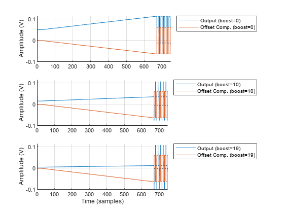
Figure. 12 - CTLE offset compensation - failed run. Notice that the CTLE output is running away till the offset engine starts to toggle between max positive and min negative value.
It appears that the offset compensation system is not working as intended: based on the behavior of the system, it appears that the feedback has an inverted polarity. That is, the integration engine is counting input samples in the wrong direction, in other words the RTL implementation is broken or the analog-digital connectivity is incorrect.
5. To fix the implementation mistake, open hdl_rtl/ctle_cm_cal.v and change line 24 from
control = control + (en? (sense? -1'sd1: 1'sd1): 1'd0);
to
control = control + (en? (sense? 1'sd1: -1'sd1): 1'd0);
6. Rerun the simulation and verify that the CTLE output now converges to zero, and that the control feedback settles to a fixed value, as shown in below, by rerunning run_offset_cal.m and plot_offset_cal.m scripts.
% After fixing the Verilog source, rerun the offset calibration Verilog testbench and plot results in MATLAB
% ctle_run_offset_cal
% ctle_plot_offset_cal
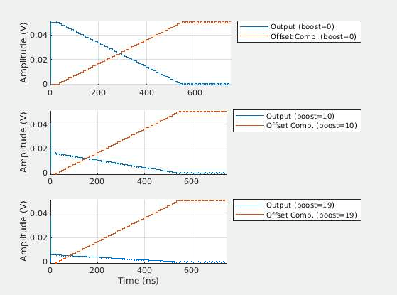
Figure. 13 - CTLE offset compensation - successful run. Notice that the CTLE output is converging towards zero and the offset compensation control (offset_comp) is converging to a steady value.
Analog Simulation-Based CTLE Model
Once the analog circuit design is complete, the designed circuit is fully characterized using a circuit simulator. The results of the analog simulations are used to create a circuit-representative Simulink CTLE model. The model provided in models/circuit_CTLE.slx represents a characterized analog CTLE, which shows differences due to implementation constraints relative to the prior specification-based CTLE model.
open_system('circuit_CTLE')A suite of small signal simulations for a properly loaded CTLE was performed for all supported boost settings. Furthermore, a suite of DC sweeps, measuring the input-to-output transfer characteristics of the CTLE, were performed for all supported boost settings. The measured curves are shown in Figure. 14. The measured frequency response of the CTLE is shown in Figure. 14(a), notice that the frequency response differs from that shown in Figure. 4(b): the width of the boost peak is wider. The DC sweeps showed that the CTLE is input limited; the input limiting nonlinearity is shown in Figure. 14(b).
(a) 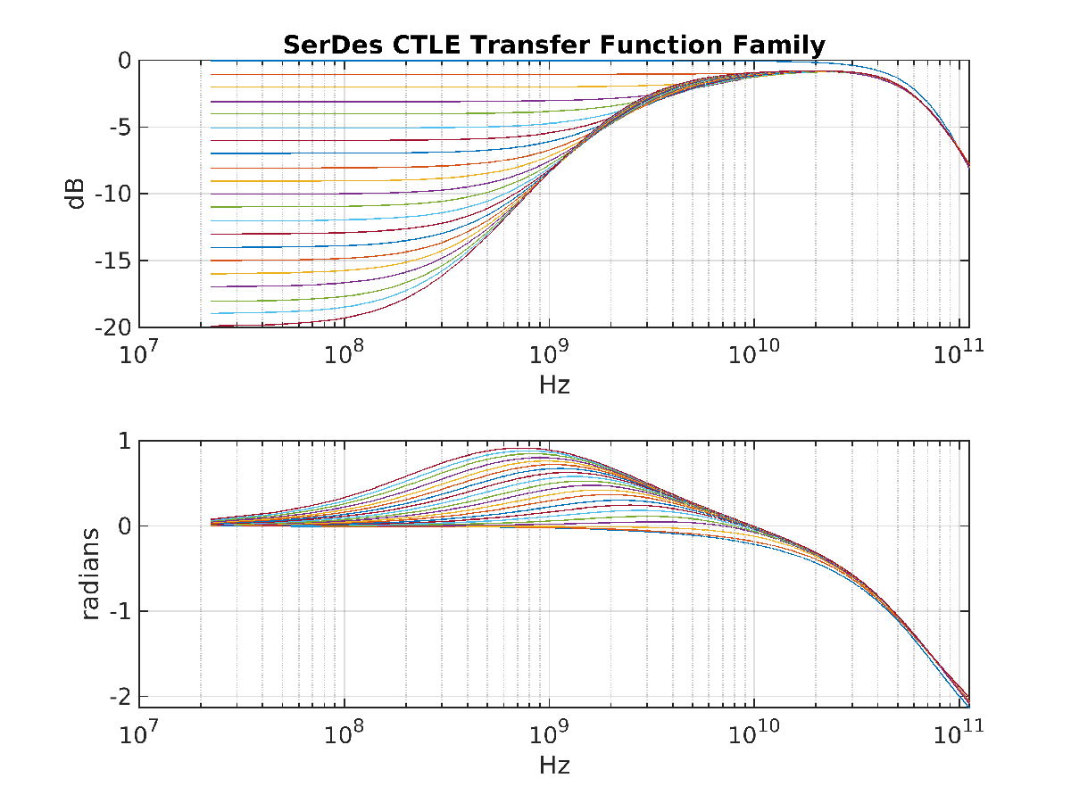 (b)
(b) 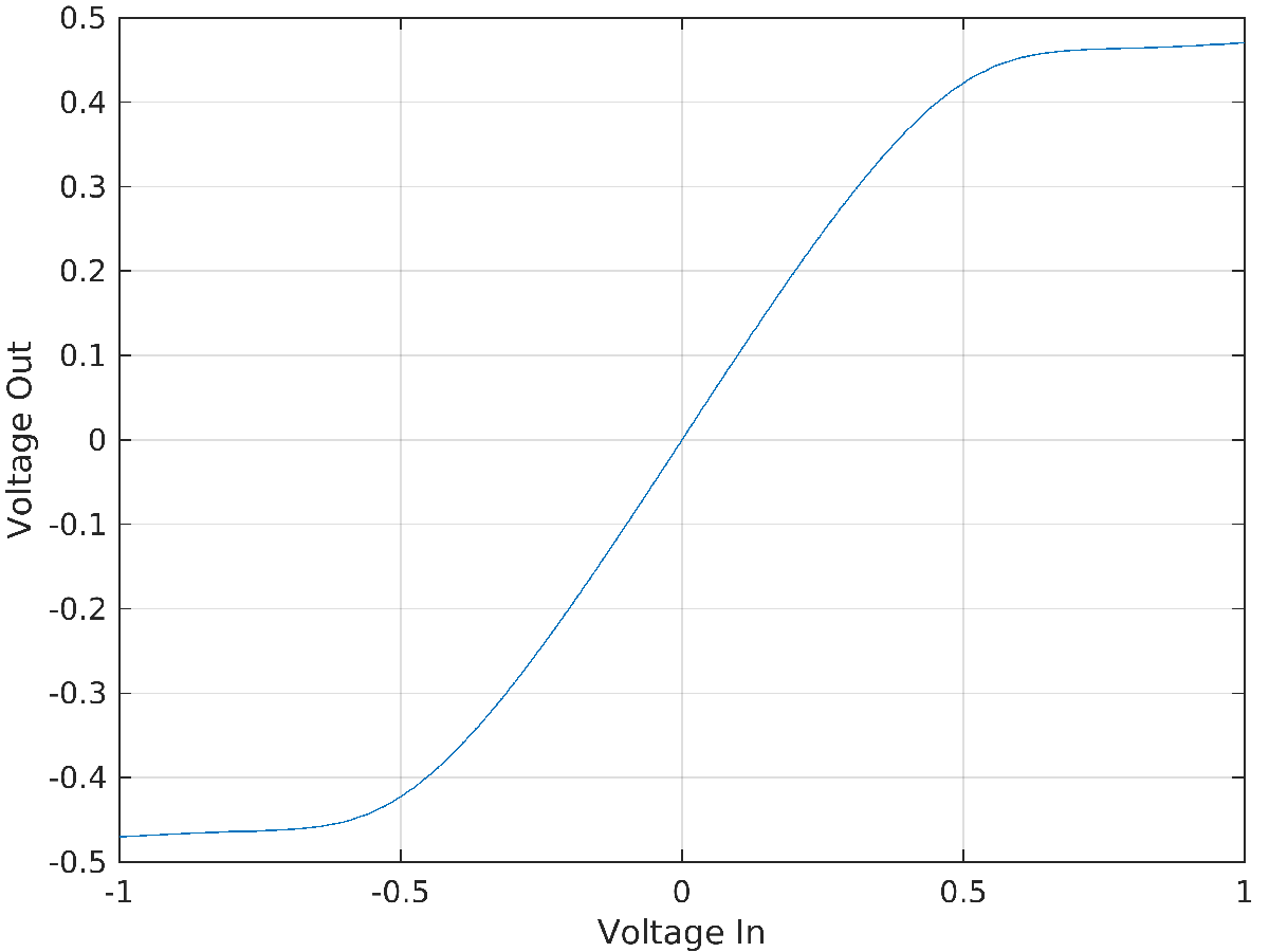
Figure. 14 - Circuit measured CTLE (a) boost-dependent gain and phase response, and (b) input-limiting non-linearity.
The resulting circuit representative CTLE model is shown in Figure. 15. Note that the saturation amplifier precedes the CTLE.
open_system('circuit_CTLE/CTLE_core')
Figure. 15 – Circuit-simulation-refreshed CTLE model – note that the non-linearity is at the input and that the nonlinearity and CTLE are based on simulation results.
The resulting model can be reexported to Verilog using the HDL Verifier tool strip. No modifications are necessary to any of the provided RTL files, including the CTLE behavioral Verilog wrapper hdl_rtl/ctle.v.
% Regenerate the SystemVerilog DPI model using the updated circuit
% representative CTLE.
slbuild('circuit_CTLE/CTLE_core')
### Searching for referenced models in model 'CTLE_core'.
### Total of 1 models to build.
### Starting build procedure for model: CTLE_core
### Starting SystemVerilog DPI Component Generation
### Generating DPI H Wrapper CTLE_core_dpi.h
### Generating DPI-C Wrapper CTLE_core_dpi.c
### Generating SystemVerilog module CTLE_core_dpi.sv using template Z:\50\hagam.Bmain.j2746022\matlab\toolbox\hdlverifier\dpigenerator\rtw\svdpi_event.vgt.
### Generating makefiles for: CTLE_core_dpi
### Invoking make to build the DPI Shared Library
### Successful completion of build procedure for model: CTLE_core

Build Summary

Top model targets:

Model      Build Reason                     Status                        Build Duration
========================================================================================
CTLE_core  Generated code was out of date.  Code generated and compiled.  0h 2m 0.69748s

1 of 1 models built (0 models already up to date)
Build duration: 0h 2m 2.5908s
% Resimulate the Simulink and Verilog and compare the results.
current_model = 'circuit_CTLE'; % set model for run script
ctle_run_cases
Reading pref.tcl

# 2022.2

# do {scripts\ctle_tb_tran_questa.do}
# 0
# Environment BOOST_VAL=0
# ** Warning: (vlib-34) Library already exists at "work".
# Errors: 0, Warnings: 1
# QuestaSim-64 vlog 2022.2 Compiler 2022.04 Apr 25 2022
# Start time: 10:47:05 on Oct 01,2024
# vlog -sv CTLE_core_build/CTLE_core_dpi.sv
# -- Compiling module CTLE_core_dpi
#
# Top level modules:
# 	CTLE_core_dpi
# End time: 10:47:06 on Oct 01,2024, Elapsed time: 0:00:01
# Errors: 0, Warnings: 0
# QuestaSim-64 vlog 2022.2 Compiler 2022.04 Apr 25 2022
# Start time: 10:47:07 on Oct 01,2024
# vlog -sv hdl_rtl/ctle_cm_cal.v hdl_rtl/ctle.v hdl_tb/ctle_tb_tran.v
# -- Compiling module ctle_cm_cal
# -- Compiling module ctle
# -- Compiling module ctle_tb_tran
#
# Top level modules:
# 	ctle_tb_tran
# End time: 10:47:08 on Oct 01,2024, Elapsed time: 0:00:01
# Errors: 0, Warnings: 0
# vsim -c -sv_lib CTLE_core_build/CTLE_core_win64 work.ctle_tb_tran "+BOOST_VAL=0"
# Start time: 10:47:09 on Oct 01,2024
# ** Note: (vsim-8009) Loading existing optimized design _opt
# //  Questa Sim-64
# //  Version 2022.2 win64 Apr 25 2022
# //
# //  Copyright 1991-2022 Mentor Graphics Corporation
# //  All Rights Reserved.
# //
# //  QuestaSim and its associated documentation contain trade
# //  secrets and commercial or financial information that are the property of
# //  Mentor Graphics Corporation and are privileged, confidential,
# //  and exempt from disclosure under the Freedom of Information Act,
# //  5 U.S.C. Section 552. Furthermore, this information
# //  is prohibited from disclosure under the Trade Secrets Act,
# //  18 U.S.C. Section 1905.
# //
# Loading sv_std.std
# Loading work.ctle_tb_tran(fast)
# Loading .\CTLE_core_build/CTLE_core_win64.dll
# CTLE_TB_TRAN: Running with boost = 0
# ** Note: $finish    : hdl_tb/ctle_tb_tran.v(52)
#    Time: 10000476 fs  Iteration: 0  Instance: /ctle_tb_tran
# End time: 10:47:13 on Oct 01,2024, Elapsed time: 0:00:04
# Errors: 0, Warnings: 0
Reading pref.tcl

# 2022.2

# do {scripts\ctle_tb_tran_questa.do}
# 10
# Environment BOOST_VAL=10
# ** Warning: (vlib-34) Library already exists at "work".
# Errors: 0, Warnings: 1
# QuestaSim-64 vlog 2022.2 Compiler 2022.04 Apr 25 2022
# Start time: 10:47:31 on Oct 01,2024
# vlog -sv CTLE_core_build/CTLE_core_dpi.sv
# -- Compiling module CTLE_core_dpi
#
# Top level modules:
# 	CTLE_core_dpi
# End time: 10:47:32 on Oct 01,2024, Elapsed time: 0:00:01
# Errors: 0, Warnings: 0
# QuestaSim-64 vlog 2022.2 Compiler 2022.04 Apr 25 2022
# Start time: 10:47:33 on Oct 01,2024
# vlog -sv hdl_rtl/ctle_cm_cal.v hdl_rtl/ctle.v hdl_tb/ctle_tb_tran.v
# -- Compiling module ctle_cm_cal
# -- Compiling module ctle
# -- Compiling module ctle_tb_tran
#
# Top level modules:
# 	ctle_tb_tran
# End time: 10:47:34 on Oct 01,2024, Elapsed time: 0:00:01
# Errors: 0, Warnings: 0
# vsim -c -sv_lib CTLE_core_build/CTLE_core_win64 work.ctle_tb_tran "+BOOST_VAL=10"
# Start time: 10:47:36 on Oct 01,2024
# ** Note: (vsim-8009) Loading existing optimized design _opt
# //  Questa Sim-64
# //  Version 2022.2 win64 Apr 25 2022
# //
# //  Copyright 1991-2022 Mentor Graphics Corporation
# //  All Rights Reserved.
# //
# //  QuestaSim and its associated documentation contain trade
# //  secrets and commercial or financial information that are the property of
# //  Mentor Graphics Corporation and are privileged, confidential,
# //  and exempt from disclosure under the Freedom of Information Act,
# //  5 U.S.C. Section 552. Furthermore, this information
# //  is prohibited from disclosure under the Trade Secrets Act,
# //  18 U.S.C. Section 1905.
# //
# Loading sv_std.std
# Loading work.ctle_tb_tran(fast)
# Loading .\CTLE_core_build/CTLE_core_win64.dll
# CTLE_TB_TRAN: Running with boost = 10
# ** Note: $finish    : hdl_tb/ctle_tb_tran.v(52)
#    Time: 10000476 fs  Iteration: 0  Instance: /ctle_tb_tran
# End time: 10:47:39 on Oct 01,2024, Elapsed time: 0:00:03
# Errors: 0, Warnings: 0
Reading pref.tcl

# 2022.2

# do {scripts\ctle_tb_tran_questa.do}
# 19
# Environment BOOST_VAL=19
# ** Warning: (vlib-34) Library already exists at "work".
# Errors: 0, Warnings: 1
# QuestaSim-64 vlog 2022.2 Compiler 2022.04 Apr 25 2022
# Start time: 10:48:00 on Oct 01,2024
# vlog -sv CTLE_core_build/CTLE_core_dpi.sv
# -- Compiling module CTLE_core_dpi
#
# Top level modules:
# 	CTLE_core_dpi
# End time: 10:48:01 on Oct 01,2024, Elapsed time: 0:00:01
# Errors: 0, Warnings: 0
# QuestaSim-64 vlog 2022.2 Compiler 2022.04 Apr 25 2022
# Start time: 10:48:02 on Oct 01,2024
# vlog -sv hdl_rtl/ctle_cm_cal.v hdl_rtl/ctle.v hdl_tb/ctle_tb_tran.v
# -- Compiling module ctle_cm_cal
# -- Compiling module ctle
# -- Compiling module ctle_tb_tran
#
# Top level modules:
# 	ctle_tb_tran
# End time: 10:48:03 on Oct 01,2024, Elapsed time: 0:00:01
# Errors: 0, Warnings: 0
# vsim -c -sv_lib CTLE_core_build/CTLE_core_win64 work.ctle_tb_tran "+BOOST_VAL=19"
# Start time: 10:48:04 on Oct 01,2024
# ** Note: (vsim-8009) Loading existing optimized design _opt
# //  Questa Sim-64
# //  Version 2022.2 win64 Apr 25 2022
# //
# //  Copyright 1991-2022 Mentor Graphics Corporation
# //  All Rights Reserved.
# //
# //  QuestaSim and its associated documentation contain trade
# //  secrets and commercial or financial information that are the property of
# //  Mentor Graphics Corporation and are privileged, confidential,
# //  and exempt from disclosure under the Freedom of Information Act,
# //  5 U.S.C. Section 552. Furthermore, this information
# //  is prohibited from disclosure under the Trade Secrets Act,
# //  18 U.S.C. Section 1905.
# //
# Loading sv_std.std
# Loading work.ctle_tb_tran(fast)
# Loading .\CTLE_core_build/CTLE_core_win64.dll
# CTLE_TB_TRAN: Running with boost = 19
# ** Note: $finish    : hdl_tb/ctle_tb_tran.v(52)
#    Time: 10000476 fs  Iteration: 0  Instance: /ctle_tb_tran
# End time: 10:48:08 on Oct 01,2024, Elapsed time: 0:00:04
# Errors: 0, Warnings: 0
ctle_plot_cases
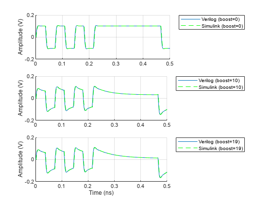
Figure. 16 – Verilog and Simulink output waveforms for circuit-representative CTLE driven by a PRBS waveform for various boost settings.
Conclusion
This example showed the flow used to generate a SystemVerilog behavioral version of a common SerDes analog block, the CTLE: the correlation of the SystemVerilog model to the original Simulink model was shown via side-by-side comparison of simulated behavior. The initial SystemVerilog behavioral model was in turn used to design and validate digital circuits used to calibrate out the input-referred offset of the CTLE. Circuit simulation derived data was then used to update the Simulink model, thereby turning it into a circuit-representative model. The SystemVerilog model was then updated to match the behavior of the updated Simulink model by regenerating the SystemVerilog model based on the updated Simulink model.
References
Validation Shift-Left: Enabling Early SerDes Mixed-Signal Validation, DesignCon 2022 conference paper, David Halupka, et al.
Find Zeros, Poles, and Gains for CTLE from Transfer Function (SerDes Toolbox)
What Are Hammerstein-Wiener Models? (System Identification Toolbox)
ADC IBIS-AMI Model Based on COM (SerDes Toolbox)