Main Content

Detect and Measure Circular Objects in an Image

This example shows how to automatically detect circles or circular objects in an image and visualize the detected circles.

Step 1: Load Image

Read and display an image of round plastic chips of various colors. Besides having plenty of circles to detect, there are a few interesting things going on in this image from a circle detection point-of-view:

  1. There are chips of different colors, which have different contrasts with respect to the background. On one end, the blue and red ones have strong contrast on this background. On the other end, some of the yellow chips do not contrast well with the background.

  2. Notice how some chips are on top of each other and some others that are close together and almost touching each other. Overlapping object boundaries and object occlusion are usually challenging scenarios for object detection.

rgb = imread("coloredChips.png");
imshow(rgb)

Figure contains an axes object. The axes object contains an object of type image.

Step 2: Determine Radius Range for Searching Circles

Find the appropriate radius range of the circles using the drawline function. Draw a line over the approximate diameter of a chip.

d = drawline;

Figure contains an axes object. The axes object contains 2 objects of type image, images.roi.line.

The length of the line ROI is the diameter of the chip. Typical chips have diameters in the range 40 to 50 pixels.

pos = d.Position;
diffPos = diff(pos);
diameter = hypot(diffPos(1),diffPos(2))
diameter = 45

Step 3: Initial Attempt to Find Circles

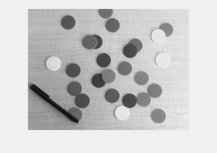
The imfindcircles function searches for circles with a range of radii. Search for circles with radii in the range of 20 to 25 pixels. Before that, it is a good practice to ask whether the objects are brighter or darker than the background. To answer that question, look at the grayscale version of this image.

gray_image = im2gray(rgb);
imshow(gray_image)
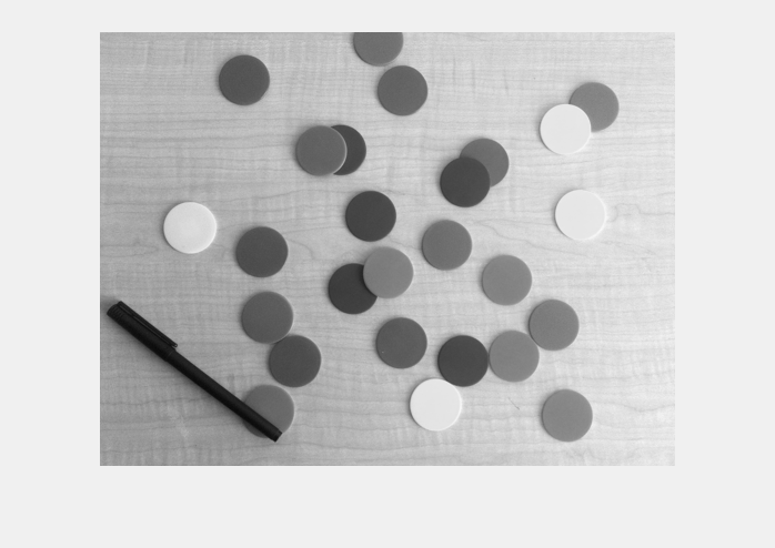
Figure contains an axes object. The axes object contains an object of type image.

The background is quite bright and most of the chips are darker than the background. But, by default, imfindcircles finds circular objects that are brighter than the background. So, specify the ObjectPolarity name-value argument to "dark" in imfindcircles to search for dark circles.

[centers,radii] = imfindcircles(rgb,[20 25],ObjectPolarity="dark")
centers =

     []


radii =

     []

Note that the outputs centers and radii are empty, which means that no circles were found. This happens frequently because imfindcircles is a circle detector, and similar to most detectors, imfindcircles has an internal detection threshold that determines its sensitivity. In simple terms it means that the detector's confidence in a certain (circle) detection has to be greater than a certain level before it is considered a valid detection. imfindcircles has a Sensitivity name-value argument that you can use to control this internal threshold, and consequently, the sensitivity of the algorithm. A higher Sensitivity value sets the detection threshold lower and leads to detecting more circles. This is similar to the sensitivity control on the motion detectors used in home security systems.

Step 4: Increase Detection Sensitivity

Coming back to the chip image, it is possible that at the default sensitivity level all the circles are lower than the internal threshold, which is why no circles were detected. By default, Sensitivity, which is a number between 0 and 1, is set to 0.85. Increase Sensitivity to 0.9.

[centers,radii] = imfindcircles(rgb,[20 25],ObjectPolarity="dark", ...
    Sensitivity=0.9)
centers = 8×2

  146.1895  198.5824
  328.8132  135.5883
  130.3134   43.8039
  175.2698  297.0583
  312.2831  192.3709
  327.1316  297.0077
  243.9893  166.4538
  271.5873  280.8920

radii = 8×1

   23.1604
   22.5710
   22.9576
   23.7356
   22.9551
   22.9995
   22.9055
   23.0298

This time imfindcircles found some circles - eight to be precise. centers contains the locations of circle centers and radii contains the estimated radii of those circles.

Step 5: Draw the Circles on the Image

The function viscircles can be used to draw circles on the image. Output variables centers and radii from imfindcircles can be passed directly to viscircles.

imshow(rgb)
h = viscircles(centers,radii);
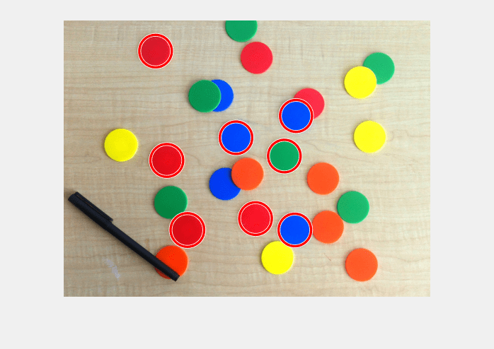
Figure contains an axes object. The axes object contains 3 objects of type line, image.

The circle centers seem correctly positioned and their corresponding radii seem to match well to the actual chips. But still quite a few chips were missed. Try increasing Sensitivity even more, to 0.92.

[centers,radii] = imfindcircles(rgb,[20 25],ObjectPolarity="dark", ...
    Sensitivity=0.92);

length(centers)
ans = 16

Increasing Sensitivity finds even more circles. Plot these circles on the image again.

delete(h)  % Delete previously drawn circles
h = viscircles(centers,radii);
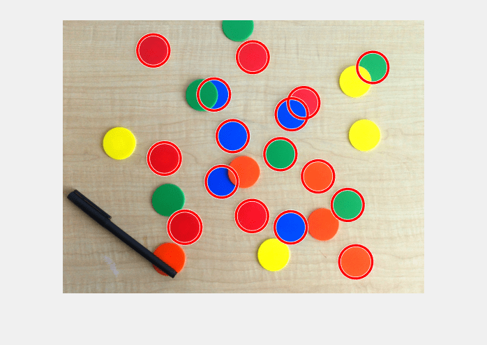
Figure contains an axes object. The axes object contains 3 objects of type line, image.

Step 6: Use the Second Method (Two-stage) for Finding Circles

This result looks better. imfindcircles has two different methods for finding circles. So far the default method, called the phase coding method, was used for detecting circles. There's another method, popularly called the two-stage method, that is available in imfindcircles. Use the two-stage method and show the results.

[centers,radii] = imfindcircles(rgb,[20 25],ObjectPolarity="dark", ...
    Sensitivity=0.92,Method="twostage");

delete(h)
h = viscircles(centers,radii);
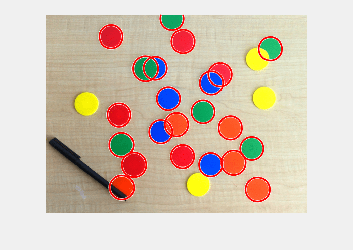
Figure contains an axes object. The axes object contains 3 objects of type line, image.

The two-stage method detects more circles at the Sensitivity of 0.92. In general, these two methods are complementary in that they have different strengths. The phase coding method is typically faster and slightly more robust to noise than the two-stage method. But it may also need higher Sensitivity levels to get the same number of detections as the two-stage method. For example, the phase coding method also finds the same chips if the Sensitivity level is raised higher, say to 0.95.

[centers,radii] = imfindcircles(rgb,[20 25],ObjectPolarity="dark", ...
          Sensitivity=0.95);

delete(h)
viscircles(centers,radii);
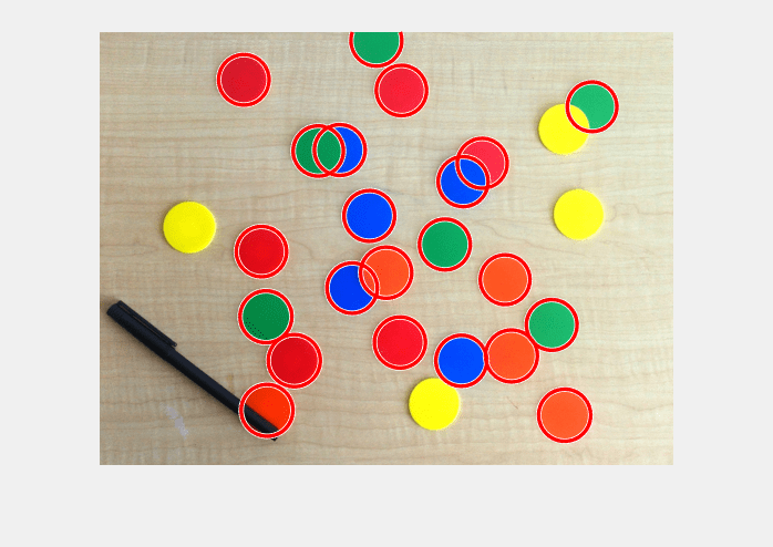
Figure contains an axes object. The axes object contains 3 objects of type line, image.

Note that both the methods in imfindcircles find the centers and radii of the partially visible (occluded) chips accurately.

Step 7: Why Are Some Circles Still Getting Missed?

Looking at the last result, it is curious that imfindcircles does not find the yellow chips in the image. The yellow chips do not have strong contrast with the background. In fact they seem to have very similar intensities as the background. Is it possible that the yellow chips are not really darker than the background as was assumed? To confirm, show the grayscale version of this image again.

imshow(gray_image)

Figure contains an axes object. The axes object contains an object of type image.

Step 8: Find Bright Circles in the Image

The yellow chips are almost the same intensity, maybe even brighter, as compared to the background. Therefore, to detect the yellow chips, change ObjectPolarity to "bright".

[centersBright,radiiBright] = imfindcircles(rgb,[20 25], ...
    ObjectPolarity="bright",Sensitivity=0.92);

Step 9: Draw Bright Circles with Different Color

Draw the bright circles in a different color, by changing the Color name-value argument in viscircles.

imshow(rgb)

hBright = viscircles(centersBright,radiiBright,Color="b");

Figure contains an axes object. The axes object contains 3 objects of type line, image.

Note that three of the missing yellow chips were found, but one yellow chip is still missing. These yellow chips are hard to find because they do not stand out as well as others on this background.

Step 10: Lower the Value of EdgeThreshold

There is another name-value argument in imfindcircles which may be useful here, namely EdgeThreshold. To find circles, imfindcircles uses only the edge pixels in the image. These edge pixels are essentially pixels with high gradient value. The EdgeThreshold name-value argument controls how high the gradient value at a pixel has to be before it is considered an edge pixel and included in computation. A high value (closer to 1) for this parameter will allow only the strong edges (higher gradient values) to be included, whereas a low value (closer to 0) is more permissive and includes even the weaker edges (lower gradient values) in computation. In case of the missing yellow chip, since the contrast is low, some of the boundary pixels (on the circumference of the chip) are expected to have low gradient values. Therefore, lower the EdgeThreshold value to ensure that the most of the edge pixels for the yellow chip are included in computation.

[centersBright,radiiBright,metricBright] = imfindcircles(rgb,[20 25], ...
    ObjectPolarity="bright",Sensitivity=0.92,EdgeThreshold=0.1);

delete(hBright)
hBright = viscircles(centersBright,radiiBright,Color="b");

Figure contains an axes object. The axes object contains 3 objects of type line, image.

Step 11: Draw Dark and Bright Circles Together

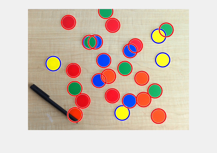
Now imfindcircles finds all of the yellow ones, and a green one too. Draw these chips in blue, together with the other chips that were found earlier (with ObjectPolarity set to "dark"), in red.

h = viscircles(centers,radii);

Figure contains an axes object. The axes object contains 5 objects of type line, image.

All the circles are detected. A final word - it should be noted that changing the parameters to be more aggressive in detection may find more circles, but it also increases the likelihood of detecting false circles. There is a trade-off between the number of true circles that can be found (detection rate) and the number of false circles that are found with them (false alarm rate).

Happy circle hunting!

See Also

| |

Related Topics