Acquire Parameterized I/Q Data from Vector Signal Transceiver by Parameter Sweeping
This example shows how to connect to a NI™ PXIe-5841 Vector Signal Transceiver (VST) and use NI-RFSA RF List Mode to configure it to return a list of time-triggered frequency and reference power level sweeps.
Connect to Instrument
Connect to a VST instrument using the ividev function. For this example, specify the driver name as niRFSA and the resource name as PXI1Slot2.
If you do not know your instrument's resource name, you can identify it from the NI Measurement and Automation Explorer (NI MAX) software. Alternatively, for simulated hardware, you can leave the resource name unspecified ("") and the IVI driver setup name-value argument as Model:5841. The driver setup is also optional. If you do not specify a name-value argument for the driver setup, ividev uses default setup values. For more information about default argument values, see ividev.
isSimulated =false; if isSimulated dev = ividev("niRFSA", "PXI1Slot2", Simulate=true, DriverSetup="Model:5841") else dev = ividev("niRFSA", "PXI1Slot2") end
dev =
  niRFSA with properties:

                    Model: "NI PXIe-5841"
             Manufacturer: "National Instruments"
             SerialNumber: ""
             ResourceName: "PXI1Slot2"
             VendorDriver: "niRFSA"
                 Simulate: 0

               ChannelIDs: "0"
          FIFOEndpointIDs: "FIFOEndpoint0"
            UserSourceIDs: "usersource0"

                 Vertical: [1x1 Vertical]
               SignalPath: [1x1 SignalPath]
              Acquisition: [1x1 Acquisition]
                 Clocking: [1x1 Clocking]
                 Triggers: [1x1 Triggers]
                   Events: [1x1 Events]
    DeviceCharacteristics: [1x1 DeviceCharacteristics]
               PeerToPeer: [1x1 PeerToPeer]
        ConfigurationList: [1x1 ConfigurationList]
    InherentIVIAttributes: [1x1 InherentIVIAttributes]
              Deembedding: [1x1 Deembedding]
          SelfCalibration: [1x1 SelfCalibration]
       FactoryCalibration: [1x1 FactoryCalibration]
        ExternalAlignment: [1x1 ExternalAlignment]
           DeviceSpecific: [1x1 DeviceSpecific]
          AcquisitionType: IQ

Show all functions
Configure Acquisition Properties
Configure the VST to acquire IQ data on channel "0". For single channel devices, you can leave the channel unspecified (""). Set the following parameters to the specified values:
Acquisition type — I/Q data
Acquisition rate — 10 MHz
ch = "0";
configureAcquisitionType(dev, "IQ");
configureIQRate(dev, ch, 10e6);
Configure Number of Waveforms and Samples per Waveform
Acquire 10 waveforms, each containing 10,000 samples of I/Q data from channel "0", as well as additional information about the acquired waveform.
finiteSamples = true;
numSamples = 10000;
numRecords = 10;

configureNumberOfSamples(dev, ch, finiteSamples, numSamples);
configureNumberOfRecords(dev, ch, finiteSamples, numRecords);
Create RF Configuration List and Add Measurements
RF configuration lists comprise configuration list steps, each of which is specified using list attributes. To create a list and configure it:
Create a configuration list by passing in attribute IDs for properties that need to change at each step. Set the new list as the active list.
Add list steps to the active configuration list. In this example, 10 different values of carrier frequency and reference level are configured.
Configure the time between steps, in seconds, by setting the time that the timer counts before generating a timer event.
dev.SignalPath.Advanced.FrequencySettlingUnits = "FSU_SECONDS_AFTER_IO";
dev.SignalPath.Advanced.FrequencySettling = 0.006;

% Step 1: Create a configuration list by passing in attribute IDs for
% carrier frequency and reference level
listName = "configList";
listAttributeIDs = ["NIRFSA_ATTR_IQ_CARRIER_FREQUENCY" "NIRFSA_ATTR_REFERENCE_LEVEL"];
numAttributes = length(listAttributeIDs);
setAsActiveList = true;
createConfigurationList(dev, listName, numAttributes, listAttributeIDs, setAsActiveList);

% Step 2: Create list steps for each discrete value of each specified attribute
numSteps = 10;
setAsActiveStep = true;

% Carrier frequencies vary from 9.9e8 to 1.01e9
carrierFreq = linspace(9.9e8, 1.01e9, numSteps);

% Power levels from vary -30 to -20 dBm
refLevels = linspace(-30, -20, numSteps);

for k = 1:numSteps
    createConfigurationListStep(dev, setAsActiveStep);
    configureIQCarrierFrequency(dev, ch, carrierFreq(k));
    configureReferenceLevel(dev, ch, refLevels(k));
end

% Step 3: Configure time between steps by:
% 1. Configuring the timer event interval
% 2. Configuring the device to wait for a digital advance trigger (which
% indicates when a new record begins)

% Change every 2 ms
dev.ConfigurationList.TimerEventInterval = 0.002;
configureDigitalEdgeAdvanceTrigger(dev, "TimerEvent", "RISING_EDGE")
Acquire Waveforms
Acquire the specified number of waveforms.
initiate(dev);
timeout = 10;
[data, waveformInfo] = fetchIQMultiRecordComplexF32(dev, ch, 0, numRecords, numSamples, timeout);
Plot Acquired Samples
Construct a frequency values vector using information from the waveformInfo structure for the first acquired waveform.
k = 1;
t0 = waveformInfo(k).relativeInitialX;
tincr = waveformInfo(k).xIncrement;
n = double(waveformInfo(k).actualSamples);
t = t0 + tincr.*(0:n-1);
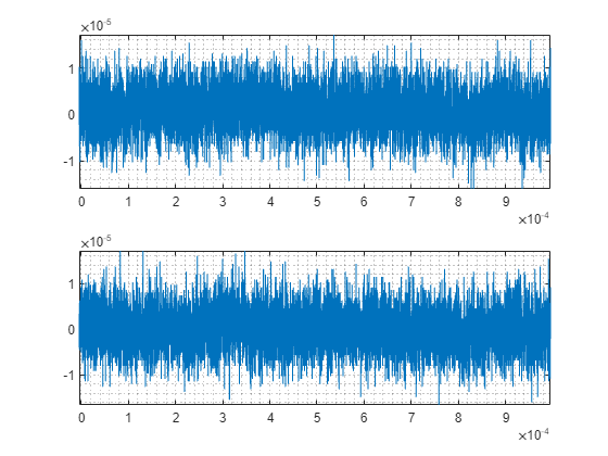
Display the I data and Q data for the first acquired waveform in related subplots.
subplot(211)
plot(t, real(data(k, :)))
axis tight
grid minor

subplot(212)
plot(t, imag(data(k, :)))
axis tight
grid minor

Clean Up
Reset the active configuration, disconnect from the instrument, and then clear the ividev object from the workspace.
deleteConfigurationList(dev, listName);
clear dev;
See Also
ividriverlist | ividevlist | ividev
Topics
- Use NI-RFSA and NI-RFSG Instrument Drivers
- Acquire Spectral Data from Vector Signal Transceiver Using NI-RFSA Instrument Driver
- Acquire I/Q Data from Vector Signal Transceiver Using NI-RFSA Instrument Driver
- Generate I/Q Data from Vector Signal Transceiver Using NI-RFSG Instrument Driver
- Generate I/Q Data from Vector Signal Transceiver Using NI-RFSG Scripting