Field-oriented Control of PMSM with Six-Step Transition
This example shows you how to implement dynamic overmodulation to control a surface-mount permanent magnet synchronous motor (SPMSM) using field-oriented control (FOC). When the motor needs to reach higher speeds or produce more torque, the control method seamlessly transitions to six-step control. This allows the motor application to achieve better range without increasing the DC bus voltage of the inverter.
This example relies on the collaborative operation of dynamic overmodulation and a specialized technique for enhanced dynamic performance. This scheme ensures a seamless transition into the six-step region while maintaining the current-loop feedback. By avoiding discrete algorithm switching, the system eliminates the torque transients and current spikes typically associated with mode transitions in industrial drives.
FOC to Six-Step Transition
PMSMs are extensively used in high-performance traction and industrial drives, yet their torque capability at high speeds is severely constrained by the limited voltage output of standard inverter control schemes. Conventional FOC utilizing linear Space Vector Pulse Width Modulation (SVPWM) leaves a significant portion of the available DC bus voltage underutilized. Most of the solutions to access this extra voltage often involve hybrid controllers that discretely switch between FOC and trapezoidal modes, introducing undesirable torque ripples and control discontinuities.
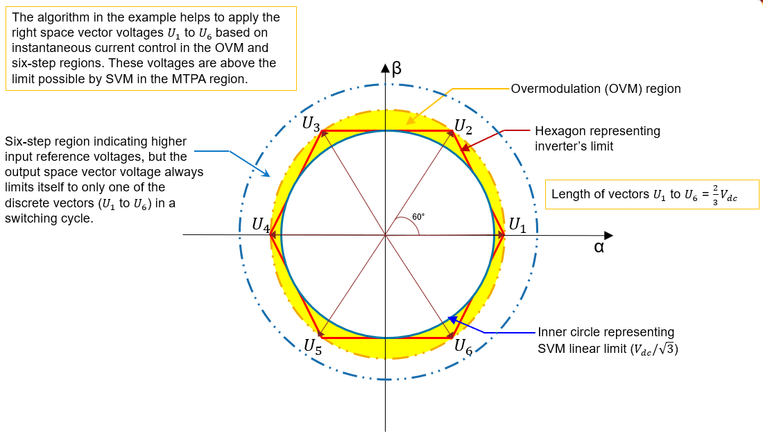
This example defines a unified control strategy that achieves a seamless transition from linear Space Vector Modulation (SVM) through the overmodulation (OVM) region up to full six-step operation, thereby extracting the maximum physical voltage potential from the inverter hardware. Unlike traditional methods, the proposed approach maintains continuous instantaneous current control within a single FOC framework, eliminating the need for mode-switching algorithms. By effectively managing controller saturation and bandwidth, the system ensures stable operation even when the voltage vector is clamped to the inverter hexagon boundary.
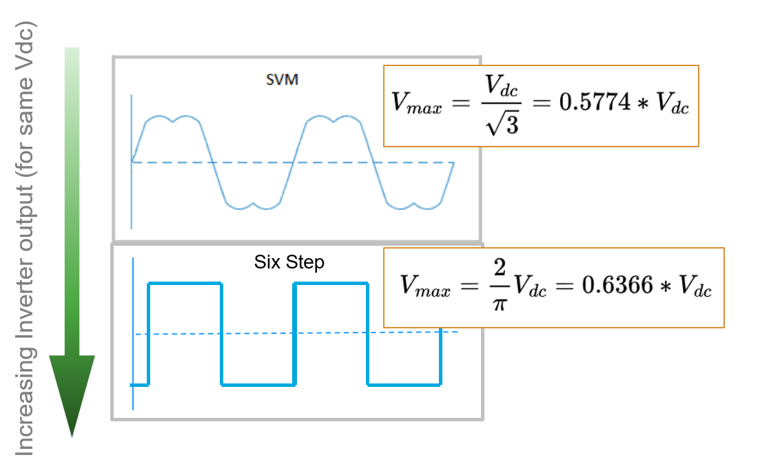
In traditional FOC using linear Space Vector Modulation (SVM), the maximum available phase voltage is restricted to . By allowing the controller to transition seamlessly into six-step mode, the fundamental voltage component increases to .
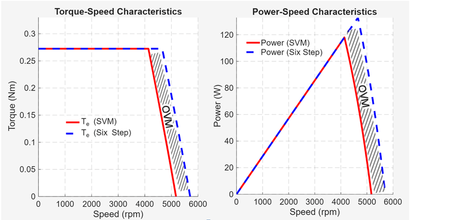
Despite the inherent increase in harmonic content during six-step operation, the drive maintains instantaneous current control. Even under stepwise torque references, the d-q currents remain well-regulated with fast transient recovery. The method adopted in this example achieves a significant enhancement in torque capability compared to standard linear control, validating its effectiveness for extending the operational envelope of high-speed drives. The gray shaded region in the below image is achieved by overmodulation and MTPA control without flux-weakening.
The six-step control algorithm in the example allows you to utilize the maximum possible voltage that can be drawn from the Inverter.
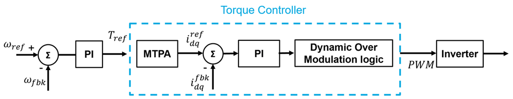
In the example, FOC to six-step transition is achieved by continuous operation of PI controllers without mode switching.
Model
The example includes the model FOCtoSixstepControlofPMSM and the host model FOCtoSixstepControlofPMSMHost.
open_system("FOCtoSixstepControlofPMSM.slx");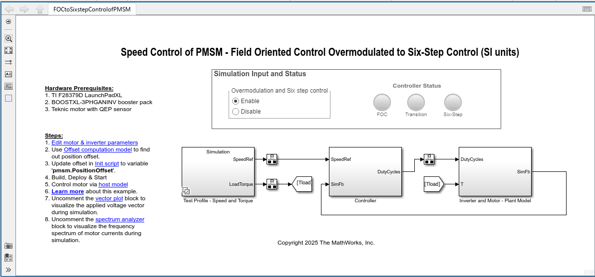
The example includes three distinct operations as a part of the controller algorithm.
FOC with space vector modulation (SVM)
Transitioning of PWM from SVM to six-step control (180° mode of conduction).
Six-Step control
Required MathWorks Products
To simulate model:
Motor Control Blockset™
To generate code and deploy model:
Motor Control Blockset
Embedded Coder®
MATLAB Coder
Simulink Coder
C2000™ Microcontroller Blockset
Required Hardware
This example supports these hardware configurations.
Motor: TeknicM-2310P (SPMSM)
Micro-Controller: Texas Instruments LAUNCHXL-F28379D
Inverter: BOOSTXL-3PHGANINV
Position sensing: Encoder based
Current Sensing: In-Line current shunts.
For connections related to the preceding hardware configurations, see LAUNCHXL-F28069M and LAUNCHXL-F28379D Configurations.
Prerequisites
1. Edit motor and inverter parameters. You can replace the values in the initialization script FOCtoSixstepControlofPMSMData.m with the values from either the motor datasheet or other sources. For details, see Estimate Control Gains and Tune Control Parameters.
However, if you have the motor control hardware, you can estimate the parameters for the motor that you want to use, by using the Motor Control Blockset parameter estimation tool. For instructions, see Estimate Motor Parameters Using Motor Control Blockset Parameter Estimation Tool. The parameter estimation tool updates the motorParam variable (in the MATLAB® workspace) with the estimated motor parameters.
2. Find out position offset of Quadrature Encoder. For details, refer to the example Quadrature Encoder Offset Calibration for PMSM and the description about the model EncoderOffsetCalibrationF28379d.slx in that example.
3. Assign the obtained position offset value to the variable pmsm.PositionOffset in the initialization script FOCtoSixstepControlofPMSMData.m.
4. Click Run on the Editor tab to run the parameter script.
Simulate Model
This example supports simulation. Follow these steps to simulate the model.
1. Open the FOCtoSixstepControlofPMSM model included with this example.
2. Click the Enable option to turn-on the simulation input required for overmodulation and six-step control.
3. Click Run on the Simulation tab to simulate the model.
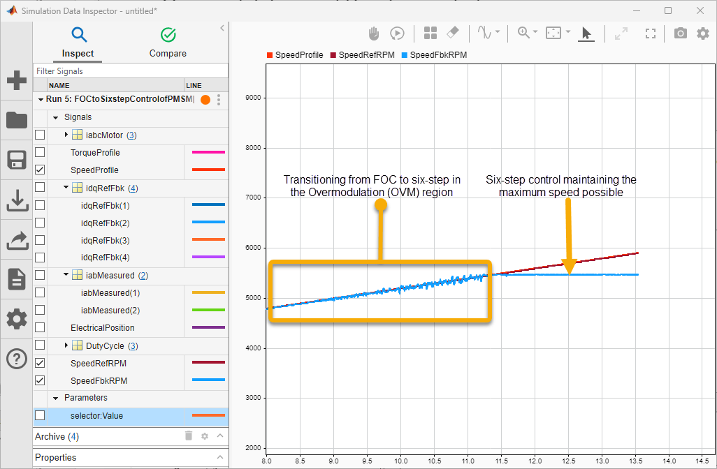
4. Click Data Inspector on the Simulation tab to view and analyze the simulation results.
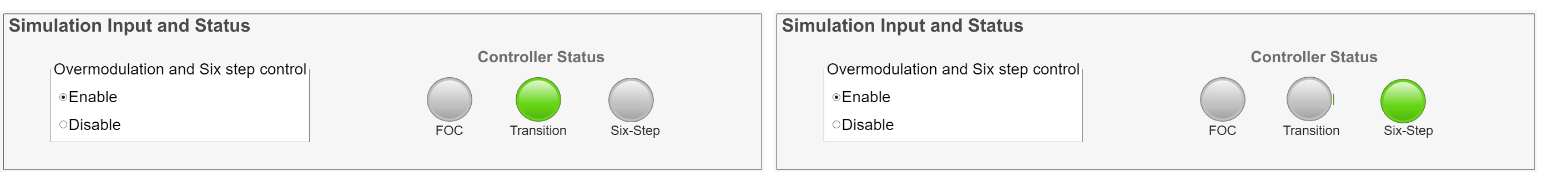
The simulation ramps up the input reference speed gradually to values that are above the base speed. In the model, you can observe the Controller Status indicating green color for the status change from FOC to Transition and finally to Six-Step.
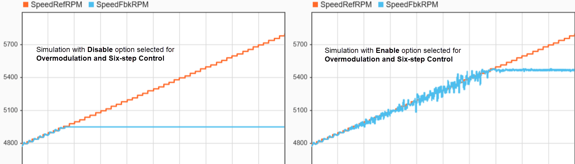
Simultaneously, in the Data Inspector, you can observe the speed transition in the overmodulation region and later the output speed remaining constant in the six-step control region (the speed which corresponds to the inverter's limit, ).
To do a comparison, you can obtain simulation results with only FOC by selecting the Disable option corresponding to Overmodulation and Six-step control in the Simulation Input and Status area in the model. In such a simulation, the output speed maintains a constant value that corresponds to SVM linear limit, and this speed is lesser that the speed that is achieved using overmodulation and six-step control.
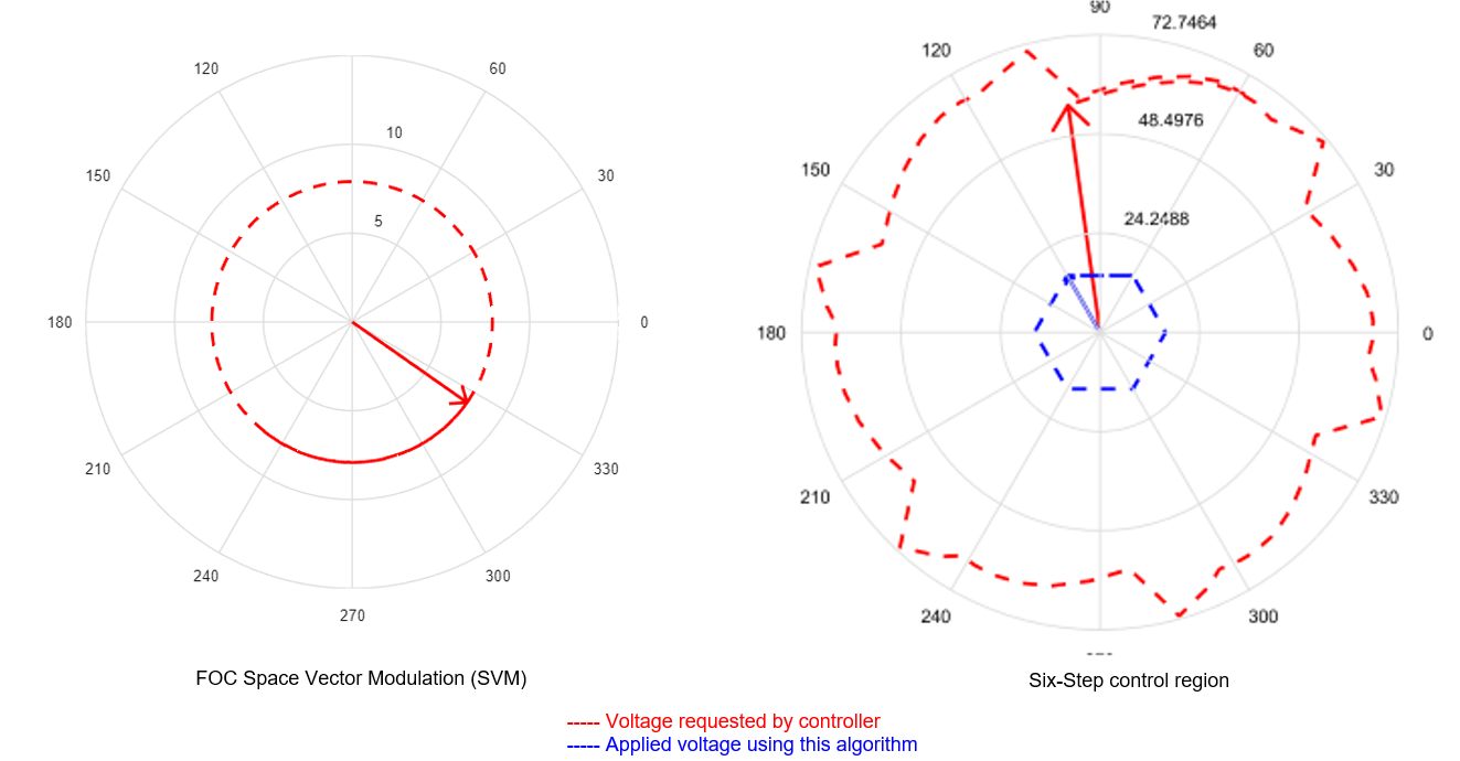
5. Disable the Comment out option for the vector plot block (to uncomment the vector plot block) to visualize the applied voltage vector during simulation.
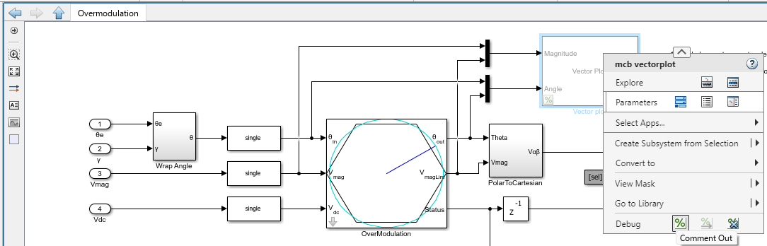
The vector plots displays the voltages when running the motor at base speed (with FOC) and above base speed (with six-step).
6. Disable the Comment out option for the spectrum analyzer block (to uncomment the spectrum analyzer block) to visualize the frequency spectrum of motor currents during simulation.
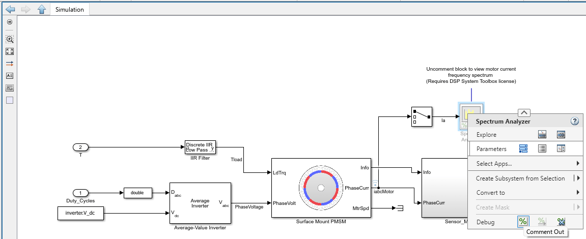
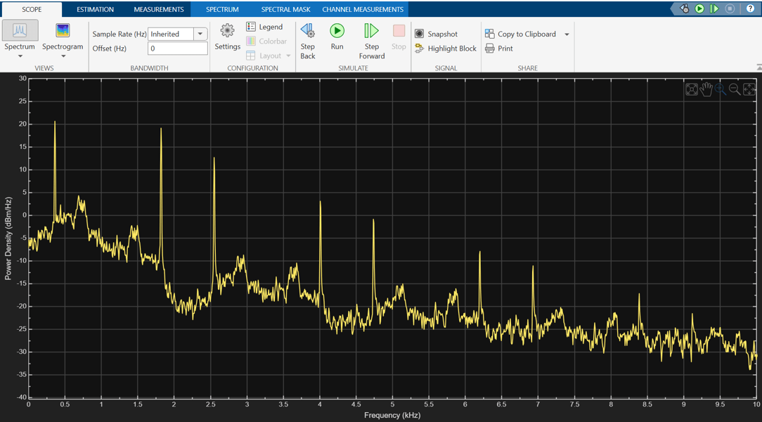
You can use the Spectrum Analyzer to visualize the frequency spectrum of motor phase current.
This figure shows the frequency spectrum of motor current when the drive is in six-step operation.
Generate Code and Deploy Model to Target Hardware
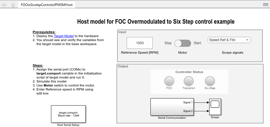
The example uses a host and a target model. The host model is a user interface to the controller hardware board. You can run the host model on the host computer. The prerequisite to use the host model is to deploy the target model to the controller hardware board.
The host model uses serial communication to command the target model and run the motor. You can use the host model to control the motor speed.
1. Complete the hardware connections.
2. Open the target model FOCtoSixstepControlofPMSM.slx.
3. Check that you have updated the correct motor and inverter parameters in the parameter script FOCtoSixstepControlofPMSMData.m
4. Click Build, Deploy & Start on the Hardware tab to deploy the target model FOCtoSixstepControlofPMSM.slx to the controller hardware.
5. Click the host model hyperlink in FOCtoSixstepControlofPMSM.slx target model to open the host model.
For details about the serial communication between the host and target models, see Host-Target Communication.
6. In the model initialization script associated with the target model, specify the communication port using the variable target.comport.
7. Update the Reference Speed value in the host model. For the particular motor used in this example, the overmodulation (transition to six-step) occurs for reference speeds above 4600rpm, and the six-step control occurs for reference speeds above 5250rpm.
8. Click Run on the Simulation tab to run the host model.
9. Change the position of the Start / Stop Motor switch to On, to start running the motor.
You can observe the LEDs in the host model that display green color for the steps in progress (FOC -----> Transition ------> Six-step).
The transition between SVM, overmodulation, and six-step mode is handled through the continuous operation of the current regulators. By avoiding discrete algorithm switching, the system eliminates the torque transients and current spikes typically associated with mode transitions in industrial drives.
References
Y. -C. Kwon, S. Kim and S. -K. Sul, "Six-Step Operation of PMSM With Instantaneous Current Control," in IEEE Transactions on Industry Applications, vol. 50, no. 4, pp. 2614-2625, July-Aug. 2014, doi: 10.1109/TIA.2013.2296652.