Open-Loop and Closed-Loop Motor Control Techniques
This section describes open-loop and closed loop motor control techniques, differences between the techniques, and their real-world applications.
In open-loop control, also known as scalar control or Volts/Hz control, the controller operates an AC motor without using any feedback from its output. In closed-loop control, the controller monitors the actual motor speed, torque, and position by adjusting control signals in real time. Each technique has advantages and disadvantages that make them useful in certain applications.
Open-Loop Motor Control
Open-loop control uses an input reference mechanical speed to determine the reference stator voltage frequency (fref) and the reference stator voltage magnitude (Vref). Because this technique does not use any feedback, it cannot make any real-time adjustments to the control input.
Instead of obtaining real-time mechanical motor position feedback from the plant, the technique processes the control input to determine the electrical motor position. The system then uses this position and the reference voltage value to generate the motor phase voltages.
You can use open-loop control in applications where dynamic response is not a concern, and a cost-effective solution is required. Open-loop motor control does not have the ability to consider external conditions that can affect the motor speed. Therefore, an open-loop control system cannot automatically correct deviations between desired and actual motor speeds.
This figure shows an open-loop control system. The power circuit consists of a PWM voltage-fed inverter supplied by a DC source. The system does not use any feedback signal for control implementation. It uses the reference speed to determine the frequency of the stator voltages.

The system computes the voltage magnitude as proportional to the ratio of rated voltage and rated frequency (commonly known as Volts/Hz ratio), so that the flux remains constant. For an AC motor:
where:
is the rated flux of the motor in Wb.
is the stator voltage of the AC motor in Volts.
is the frequency of the stator voltage and currents of the AC motor in Hz.
In an open-loop system, the speed for an AC motor is expressed as:
where:
is the mechanical speed of the AC motor in rpm.
is the number of pole pairs of the motor.
The following equation then determines the frequency of the reference voltages, fref, needed to reach a required reference speed, RPMref (for a given machine).
By maintaining a constant flux equal to the rated flux of the motor, the system maintains a constant ratio of rated voltage to rated frequency:
The system uses this constant ratio to compute the peak amplitude of PWM reference voltages (Vref) from the reference voltage frequency (fref).
The open-loop system uses fref and Vref along with the computed electrical motor position to generate the PWM duty cycles for the inverter.
By keeping the ratio of reference stator voltage Vref and reference frequency fref constant for three-phase voltage waveforms, the system keeps the stator magnetic flux relatively constant. However, as shown in this figure, the V/F ratio does not remain constant throughout the entire range of motor speed.
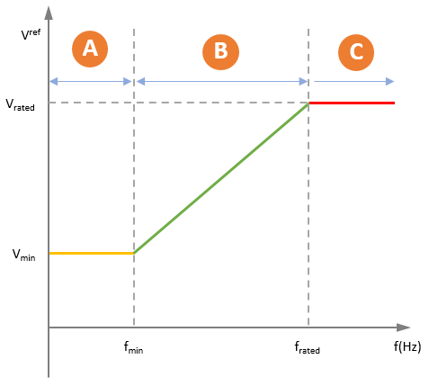
Region A — At lower speeds, the system needs a minimum boost voltage (15% or 25% of the rated voltage) to overcome the effect of the stator resistance voltage drop. The voltage Vmin acts as a compensation for this drop.
Region B — In this region, the system keeps the Vrated / frated ratio constant. It follows V/F control by computing Vref according to fref.
Region C — At higher speeds, the system cannot maintain a constant V/F ratio because the stator voltages are limited to Vrated. In this region, Vref remains equal to Vrated even when there is a rise in fref.
Operating the motor at rated flux helps avoid motor overheating and helps increase motor efficiency by balancing generated torque and power consumed. In addition to simplifying the control algorithm, using rated flux makes the motor behavior more predictable.
An open-loop control system does not assess or correct the plant output for internal and external disturbances that affect motor speed, such as changes in motor load. Therefore, the system cannot automatically correct the deviation between the desired and the actual motor speeds.
When using the per-unit system representation, the open-loop control system considers Vrated as the base quantity, which usually corresponds to 1PU or 100% duty cycle. (Using sinusoidal pulse-width modulation (PWM) as opposed to space vector PWM requires an additional gain of ). For more information, see Per-Unit System.
For an example showing how to run a three-phase motor using open-loop control, see Run 3-Phase AC Motors in Open-Loop Control and Calibrate ADC Offset.
Note
The open-loop control implementation described here does not compensate for voltage drops due to the stator resistance and field weakening.
Closed-Loop Motor Control
Closed-loop control uses real-time feedback from the motor, such as current and mechanical position, to make comparisons between reference input and actual output (speed, torque, or position). It then makes the necessary corrections to the reference voltages and duty cycles to minimize any error so that the motor output matches the reference input.
Using real-time plant feedback, a closed-loop system can provide precise control of motor speed, position, or torque. Unlike open-loop control, a closed-loop system automatically compensates for internal and external disturbances such as change in motor load. You can use the control parameters (controller gains) to tune and optimize responsiveness, accuracy, and stability of the control system.
Use closed-loop control in applications where precision, adaptability, and efficiency are crucial such as in robotics, drones, electrical vehicles, and industrial automation systems.
The key components of a closed-loop motor control system are:
Motor — A motor or actuator that the system runs by controlling characteristics like speed, torque, and position, for instance a permanent magnet synchronous motor (PMSM) or an AC induction motor (ACIM).
Sensors — Devices that can measure the actual motor output such as position and current sensors. Position sensors like quadrature encoder, resolvers, and Hall effect sensors measure the real-time rotor mechanical position. Analog-to-digital converters (ADCs) measure the motor phase currents and provide their equivalent digital count values.
Controller — A device or algorithm that processes the sensor outputs, compares them with the control inputs, and adjusts the control signals that generate motor phase voltages.
Inverter or Driver — A device that converts the control signals from the controller into three-phase voltages that drive the motor.
Any closed-loop motor control technique follows these steps in a loop:
Establish a setpoint — Establish a desired speed, torque, or position as a setpoint or control input.
Measure feedback — Use sensors or sensorless algorithms to measure plant feedback, including motor position and phase currents.
Comparison — Compare plant feedback with the control system setpoint and compute the difference or error value.
Correction — Use the difference or error to calculate and apply necessary adjustments to the control signals.
Actuation — Use the adjusted control signals to modify the phase voltages such that the plant output matches the setpoint.
Vector Control
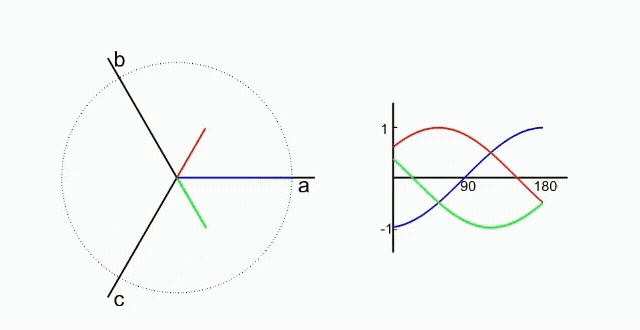
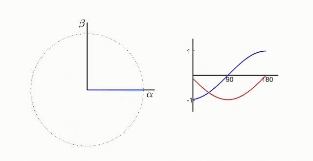
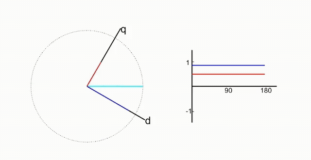
Vector control (or d-q current control) is a common closed-loop current control technique used to control three-phase AC motors. The technique first uses the Clarke transform to convert the three-phase currents to the α-β stationary reference frame. It then uses the Park transform to convert the currents to the rotating d-q reference frame, where the currents are represented by DC signals. The figures below illustrate normalized time-domain phase currents in the three frames.
Controlling motor phase AC currents directly using PI controllers results in a delayed tracking response because of the limited ability to use higher gains for reducing the steady state error.
However, using d-q equivalents of motor phase currents and voltages increases control efficiency and performance with the PI controllers. Because integral control leads to minimum steady-state error and a very high DC gain, PI controllers show very high efficiency when controlling DC signals.
The vector control strategy takes advantage of this efficiency by using PI controllers to control the d-q axis currents (control inputs) and generate the d-q axis voltage outputs (control signals) with zero steady-state error. The algorithm then uses mathematical transforms to convert these voltages into duty cycles for the inverter, which drives the motor by using the corresponding three-phase voltages.
A vector control algorithm ensures that the rotating d-q reference frame is synchronized with the three-phase stator voltages, such that both have identical frequency and position.
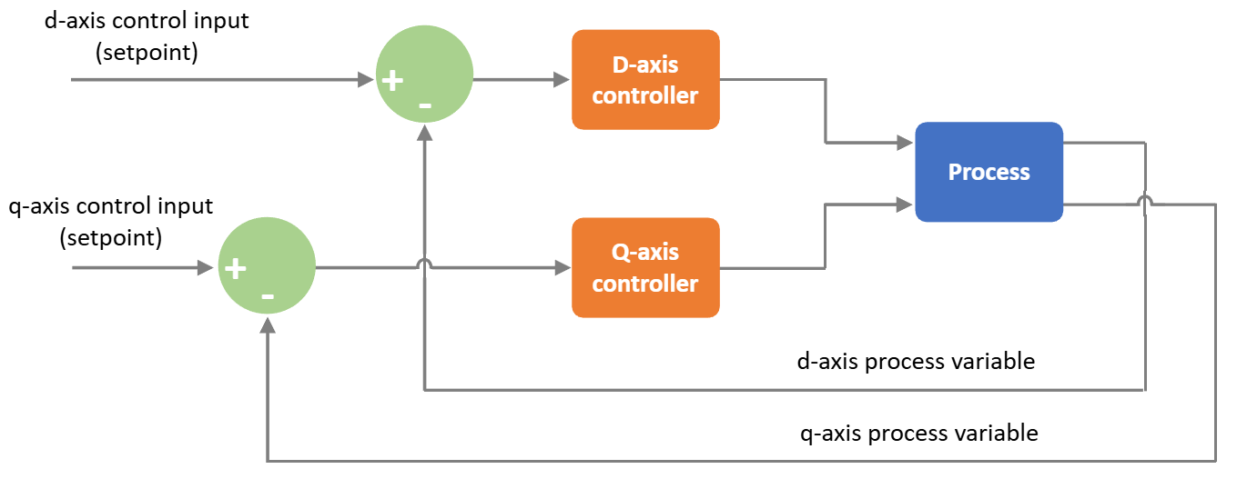
The following figure shows the general principle of vector control.
The following figure shows a modelling approach to implementing vector control:
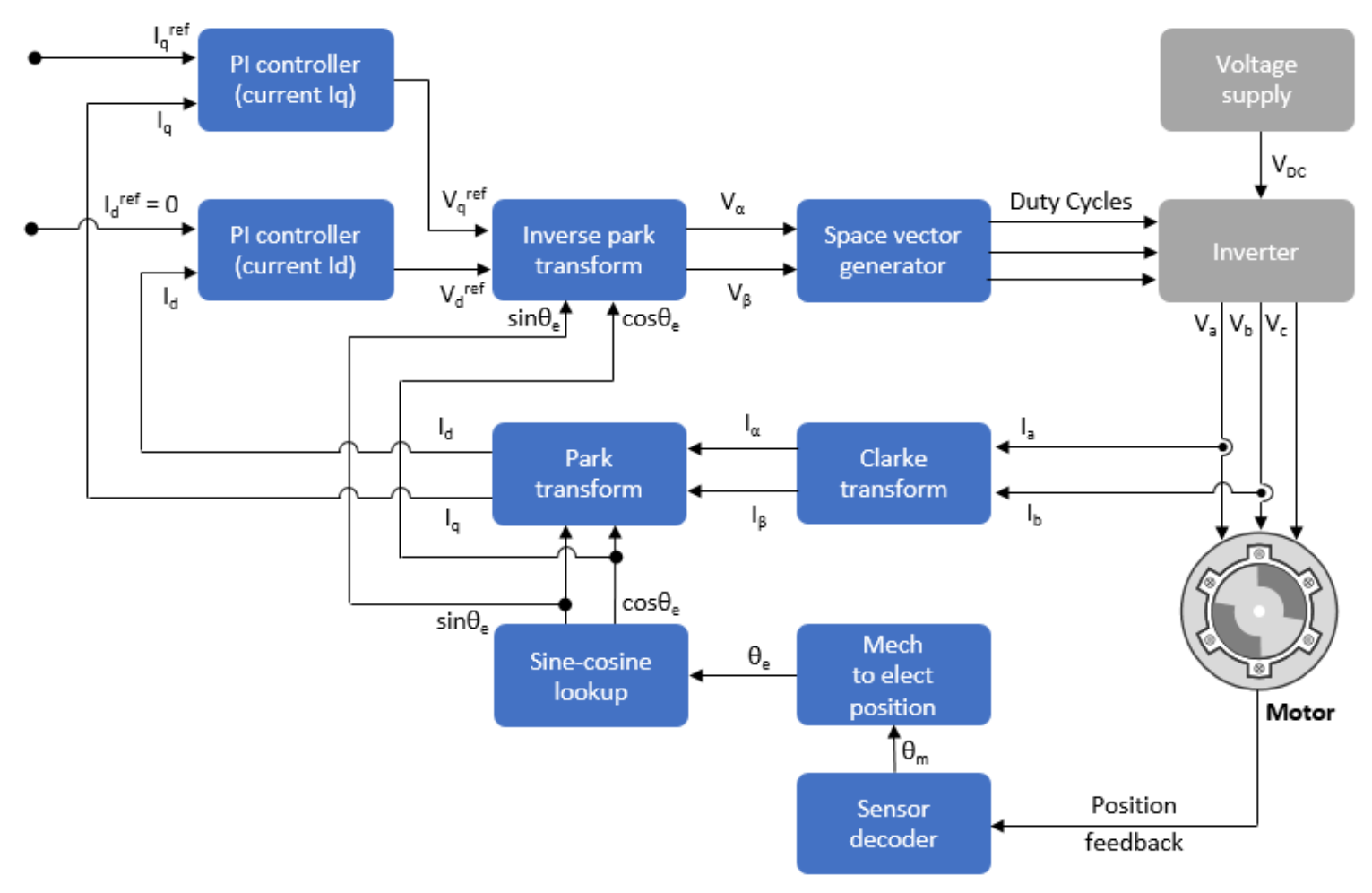
The algorithm uses two PI controllers to independently control d-axis and q-axis currents. These PI controllers supply d-q axes voltages as control signals. The algorithm then uses the inverse Park transform to convert these voltages into their α-axis and β-axis equivalents in the stationary orthogonal reference frame. FOC uses a modulation technique, such as PWM modulation, that utilizes these voltages to generate the duty cycles to drive the inverter.
Transforming the currents to the d-q axes requires rotor mechanical position feedback, which you can obtain using position sensors or sensorless position estimators.
In your algorithm, you can model the lag during current measurement using sampling delays. Similarly, you can use a delay to model the computation time needed to execute the control algorithm.
For accurate results, you must tune the PI controllers gains appropriately. For more details about solutions that Motor Control Blockset™ provides for tuning the controller gains, see Gain Calculation and Tuning.
Open-Loop to Closed-Loop Transitions
Some applications require you to start the motor using open-loop control. Once the motor achieves the minimum required stability in open-loop control, the control system shifts to closed-loop control.
In a quadrature encoder-based position sensing system, the motor starts up in open-loop control and transitions to closed-loop control once the index pulse is detected. For details, see Simulate Calculation of Rotor Position Using Quadrature Decoder Block.
In sensorless position control, the motor starts running at 10% of the base speed in the open-loop configuration. After the reference switch goes beyond 10% of the base speed, the control system transitions from open-loop to closed-loop control. To ensure smooth transition from open-loop to closed-loop control, the PI controllers reset and start from the same initial condition as the open-loop outputs. To learn more about switching sensorless position control of permanent magnet synchronous motor (PMSM) from open-loop to closed-loop, see Sensorless Field-Oriented Control of PMSM.