Lane Change Assist Using Nonlinear Model Predictive Control
This example shows how to design a lane-change controller using a multistage nonlinear model predictive control (MPC). In this example, you:
Review a control algorithm that combines a custom AStar path planning algorithm and a lane-change controller designed using the Model Predictive Control Toolbox™ software.
Design a multistage nonlinear MPC controller for autonomous lane changing.
Test the closed-loop control system in a Simulink® model using driving scenarios generated using Automated Driving Toolbox™ software.
Introduction
A lane change assist control system autonomously steers an ego vehicle to an adjacent lane when there is another vehicle moving slower in front of it, as shown in the following figure.

The lane change controller in this example is designed to work when the ego vehicle is driving on a straight road at a constant velocity, though it can be extended to other driving scenarios with appropriate modifications.
In this example:
A driving scenario is used to model the environment such that a situation requiring a lane change arises. The scenario was created and exported using the Driving Scenario Designer app from the Automated Driving Toolbox.
Based on this scenario, a discrete occupancy grid is populated, which is then used by the path planner to plan a collision-free reference path for the ego vehicle.
Once the reference path is generated, the controller performs the autonomous lane change maneuver by controlling the steering angle of the ego vehicle to track the lateral position of the planned path.
Overview of Simulink Model
Open the Simulink model.
mdl = 'LaneChangeExample';
open_system(mdl)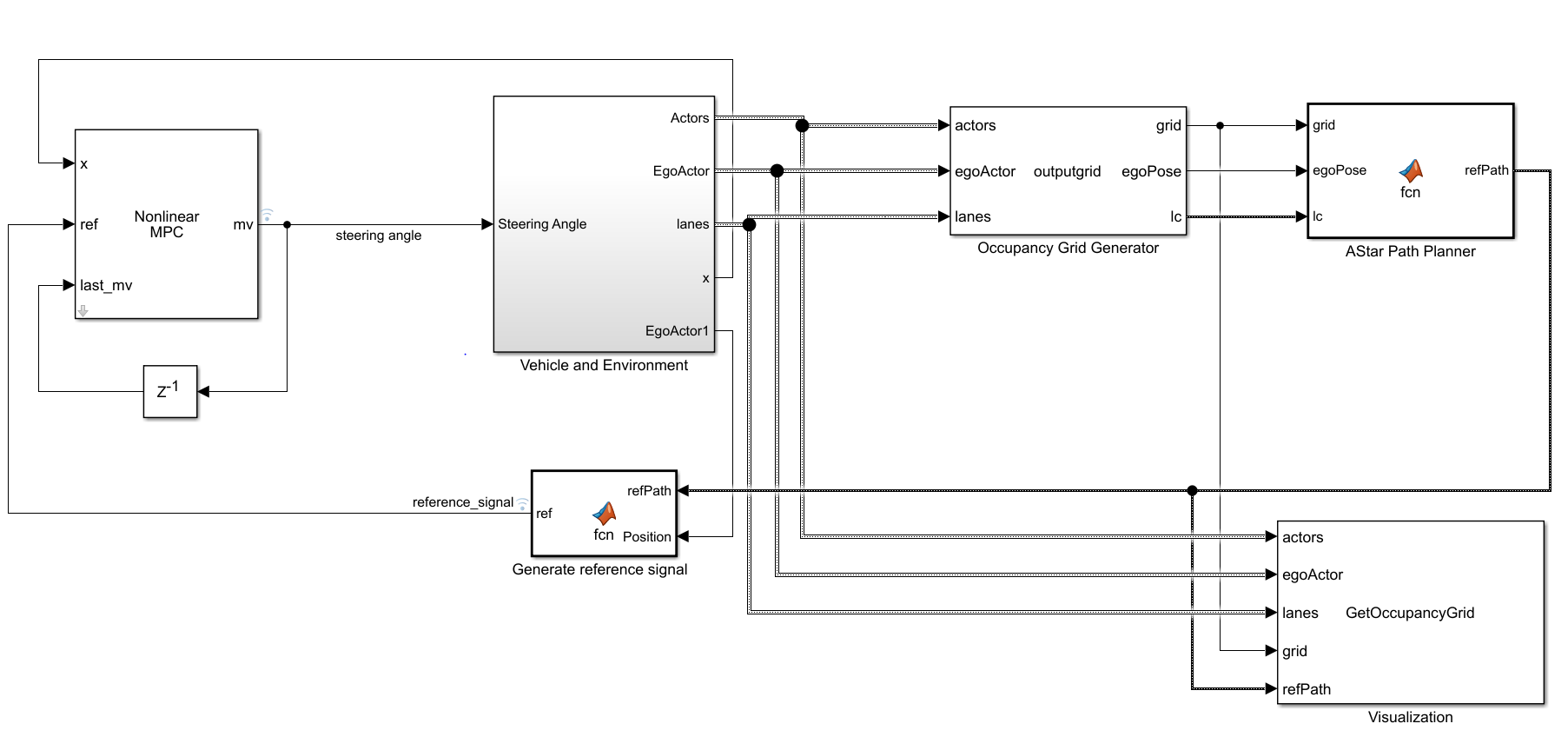
The model contains four main components:
Nonlinear MPC — Lane change controller, which controls the front steering angle of the ego vehicle
Vehicle and Environment — Models the motion of the ego vehicle and models the environment
Occupancy Grid Generator — Generates a discrete grid that contains information about the environment and cars surrounding the ego vehicle
AStar Path Planner — Plans a collision-free path for the ego vehicle considering the dynamic behavior of other cars
Inside the Vehicle and Environment subsystem, the Vehicle Dynamics subsystem models the vehicle dynamics using the Bicycle Model - Velocity Input block from the Automated Driving Toolbox.
Opening this model runs the helperLCSetUp script, which initializes the data used by the Simulink model, such as the vehicle model parameters, controller design parameters, road scenario, and surrounding cars.
The multistage nonlinear MPC controller for this example is designed using the createNLmpcObjLC function, which is called from the helperLCSetUp script. This controller uses the state equations defined in vehicleStateFcnLC.m and controls the steering angle of the ego vehicle.
Plot the scenario with the road and the cars that the ego vehicle will encounter.
plot(scenario)
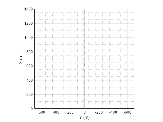
The following figure shows a zoomed-in portion of the road.

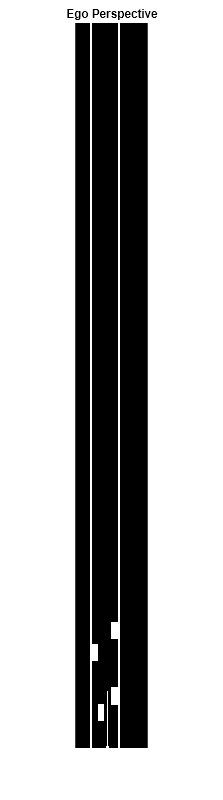
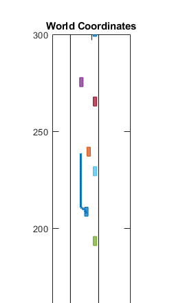
Simulate the model to the end of the scenario. Simulating the model opens the Bird's Eye Plot in World Coordinates and the occupancy grid in Ego Perspective. The occupancy grid shows a representation of the road and vehicles in front of the ego vehicle and includes the planned path as a white line.
out = sim(mdl);
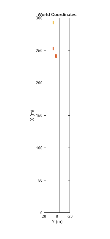
During the simulation, the Bird's Eye Plot shows the planned path in blue.
To plot the results of the simulation and depict the ego vehicle surroundings, you can also use the Bird's-Eye Scope (Automated Driving Toolbox). The Bird's-Eye Scope is a model-level visualization tool that you can open from the Simulink toolstrip. On the Simulation tab, under Review Results, click Bird's-Eye Scope. After opening the scope, set up the signals by clicking Find Signals. Once the signals are set up and the simulation is running, you can view the lane change maneuver performed by the ego vehicle in the World Coordinates View of the Bird's-Eye Scope.

Plot the controller performance.
plotLCResults
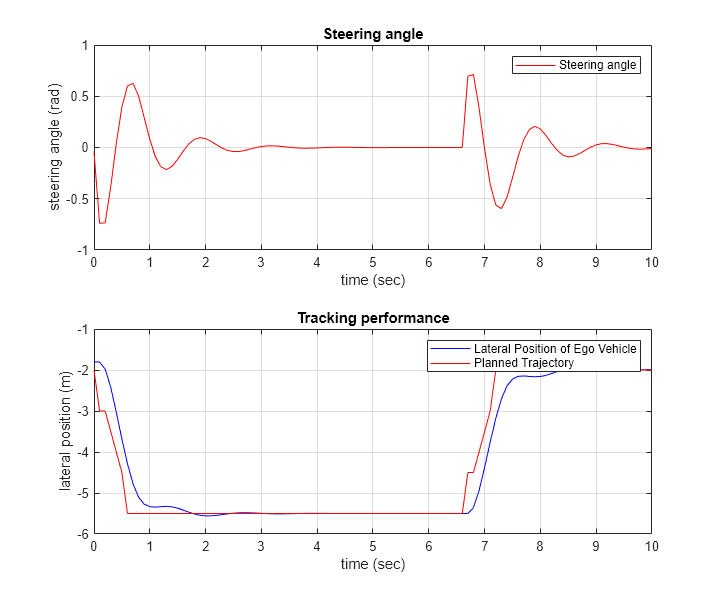
The figure shows the lane change performance of the controller.
The Steering angle plot shows that the steering angle for the ego vehicle follows that of a standard lane change maneuver.
The Tracking performance plot shows that the multistage nonlinear MPC controller does a satisfactory job tracking the lateral position of the reference path from the AStar path planner.
Run Controller for Multiple Test Scenarios
This example includes an additional test scenario. To verify the controller performance, you can test the controller for multiple scenarios and tune the controller parameters if the performance is not satisfactory. To do so:
Select the scenario by changing
scenarioIdinhelperLCSetUp. To use the additional scenario, setscenarioId = 2.Configure the simulation parameters by running
helperLCSetUp.Simulate the model with the selected scenario.
Evaluate the controller performance using
plotLCResults.Tune the controller parameters if the performance is not satisfactory.
Conclusion
This example shows how to implement an integrated autonomous lane change controller on a straight road with a reference path generated from an AStar path planner and test it in Simulink using driving scenarios generated using Automated Driving Toolbox software.